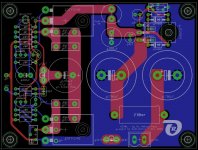
James, I have in the meantime drawn a layout for "one-half of a bridged ACA" (according to your proposals) and have already soldered and listened to a prototype of it.
I am driving this ACA from a 24VDC regulated PSU, consisting of a 2x19VAC/160VA torroid, full bridge-rectifier (mounted on the heatsink), 10mF reservoir caps
and LM1084 regulator, adjusted to 24VDC.
I would never think about driving a ClassA AMP from a SMPS.
This ACA alone already plays beautifully, but I would like and bridge it , same as you did.
Can you please tell me, how to proceed with ACA#2?
For the ACA#2 I need an inverse input-signal (which can be derived from the output of ACA#1).
Is a "bridging resistor" (value: 68,1K, from where to where?) all that I need?
Don't I need a resistor-divider (same like in feedback)?
Once I am done with my "bridged-ACA", I will happily send you a pair of my PCBs.
Best regards - Rudi_Ratlos
Attachments
Last edited:
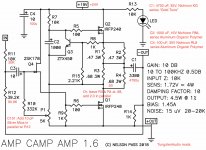
Rudi, glad you are moving forward with your own mods to the ACA. I have not seen another build using integrated regulator ICs for the 24V power. To make a bridged amp, you just need to add the 68.1 kOhm resistor from the left (–OUT) terminal to the right (+IN) input. This is commonly done through a switch as shown in Step 38 of the excellent Amp Camp Amp V1.6 Build Guide by 6L6. Note that it is also necessary to tie the two (+OUT) terminals together with a heavy piece of wire, which is also shown. These steps may be easier if the two boards are in one chassis.
The speaker wires will then be connected as shown in Step 54, with the black (–) wire connected to the left (–OUT) terminal, and the red (+) wire connected to the right (–OUT) terminal.
Now you need to build two more boards the same way for the other channel of your stereo system.
I have been quite happy with the sound of my bridged ACAmps powered by the kit SMPS power supplies. I must admit that I was skeptical at first, and some of my capacitor upgrades were intended to address any residual noise issues that may have been caused by the little brick supplies. Regardless, the system sounds quite fine, and I'm currently pursuing some other builds.
how's that nobody asked for SUSY ACA ?

SUSY ACA PLEASE!!
how's that nobody asked for SUSY ACA ?
No doubt there are a myriad of mighty wackoo ideas to try.
I already have schematics for a higher voltage ACA with IRFP150s and a cascoded input follower, an ACA with double IRFP240s in the output, and one with an FET cap multiplier on the power rail.
How about an ACA headphone amp or an ACA-X (or is that X-ACA)? Certainly there must be a Son of ACA, Babelfish ACA and a Bride of SoACA! Should keep the Greedy Boyz busy for a little while.
Among other things, I'm working on an ACA with a Zen V4 input buffer. I've got a few ZVP3310A and ZVN3310A Fets to play with. You know, just in case the 2SK170s get scarce.

Hello
i am rather a newbie in such things, so maybe you could give a little help to me
So now R11 is 20k and R12 is 90.9k?
Hmmm... so now we have
0.68R II 2R II 0.68R -> 0.291R
Or
0.68R II 2R II 2R II 0.68R -> 0.254R
Maybe better said, did i need *one* 2Ohm resistor or *two*?
thanks Joachim
i am rather a newbie in such things, so maybe you could give a little help to me
I changed the input resistor R11 to 20k and the feedback resistor to 90.9k.
So now R11 is 20k and R12 is 90.9k?
Shortly after making this change, I also added a 2.0 Ohm resistor in parallel to R3 and R4,
Hmmm... so now we have
0.68R II 2R II 0.68R -> 0.291R
Or
0.68R II 2R II 2R II 0.68R -> 0.254R
Maybe better said, did i need *one* 2Ohm resistor or *two*?
thanks Joachim
Nice work, Rudi!
I like this layout and use of integrated VR.

Although I find SMPS followed by DC-DC step up and then a cap multiplier and a CRC works great and sounds great too. Many folks are doing this with the MoFo I think as the DC-DC has adjustable output and you can set the final voltage to whatever suits you.
I like this layout and use of integrated VR.
Although I find SMPS followed by DC-DC step up and then a cap multiplier and a CRC works great and sounds great too. Many folks are doing this with the MoFo I think as the DC-DC has adjustable output and you can set the final voltage to whatever suits you.
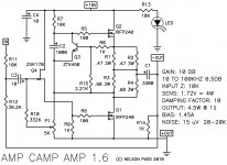
With the new ACA kits becoming available, I wanted to post this for those who might be interested in performing a few 'tweaks' to what remains an excellent design.
I have found the modified design to have improved clarity and spatial detail. I will also not that one of the best things to do with the modified design is to build two complete kits and run them as bridged monoblocks. Using a separate power supply for each channel makes very noticeable improvements in dynamics and imaging.
If one has chosen to use single-ended inputs (as I currently have), a bridging resistor of 68.1k Ohms will be necessary. Please refer to the ACA build guide and previous posts in this thread for the installation of the bridging resistor.
Attachments
Last edited:
With the new ACA kits becoming available, I wanted to post this for those who might be interested in performing a few 'tweaks' to what remains an excellent design.
I have found the modified design to have improved clarity and spatial detail. I will also not that one of the best things to do with the modified design is to build two complete kits and run them as bridged monoblocks. Using a separate power supply for each channel makes very noticeable improvements in dynamics and imaging.
If one has chosen to use single-ended inputs (as I currently have), a bridging resistor of 68.1k Ohms will be necessary. Please refer to the ACA build guide and previous posts in this thread for the installation of the bridging resistor.
"I will also not that one of the best things to do with the modified design is to build two complete kits and run them as bridged monoblocks."
Are you saying it is, or isn't a good idea to run this modified design as bridged mono blocks?
"I will also not that one of the best things to do with the modified design is to build two complete kits and run them as bridged monoblocks."
Are you saying it is, or isn't a good idea to run this modified design as bridged mono blocks?
It's definitely a good idea! This amp sings as bridged monoblocks.
Typo: meant to say *note*
It's definitely a good idea! This amp sings as bridged monoblocks.
Typo: meant to say *note*
If only my de-soldering skills were legit... might have to scoop 4 more pcbs and try this
... Haven't seen mention of your using your modified ACA's in parallel monoblock configuration which requires the bridging resistor to be removed.
Any potential difficulty using ACA's modified to your schematic spec in parallel monoblock?
The way I have wired my bridged monoblocks allows the bridging resistor to be removed by flipping the toggle switch on the rear panel. This allows them to be run as individual stereo amps.
With some clever external wiring, a pair of stereo amps could be made to function as parallel monoblocks. A 'Y' adapter for the RCA inputs and some banana plug jumpers to connect the speaker outputs in parallel... I haven't tried this yet myself, but I don't see any potential issues. If anything, the 20k input impedance will help make the modified boards easier to drive when they are wired in parallel. I will leave this to the readership to discuss.
Last edited:
ACA parallel monoblock configuration
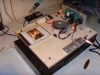
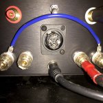
Given that some of the other ACA builders have kindly provided such an easy working solution (see post #6522 of the Amp Camp Amp - ACA thread), I finally had to try this for myself. If one already has a pair of ACAmps built according to the ACA 1.6 Build Guide, then it is very straightforward to take a couple extra steps to wire them as parallel monoblocks. I took the easy way and got a pair of male XLR connectors from my local electronics surplus store. Using just the 3-pin insert, I jumpered pins 2 & 3 together and plugged the inserts into the XLR sockets on the back of my ACAmps. There are several ways to tie the outputs of the two boards together. I've attached a photo of how I did it. I recommend checking out the other photos in the post that I linked above.
Again, this amp just sings when using a pair as monoblocks! Comparing the parallel mono configuration to the bridged mono, I would say the parallel monoblocks have a more even presentation across the audio frequency spectrum. They also seem to preserve the spatial information of every recording in slightly better detail, at least in my system. I've probably given a slight bump to the volume control for most of the albums I've listened to since making the switch, but it's a very small boost and the amps seem to have an easier time driving my old Vandersteens.
I should mention that I recently finished building a new power supply for my preamp, and have been pleasantly surprised at how much of an improvement this has given to my system overall. My Naim NAC 82 preamp was previously powered by a single HiCap (Olive era). It is now powered by my DIY build of a dual HiCap DR. The most surprising aspect of the sound with the new PSU is how much taller and deeper the soundstage presentation is. The speakers just disappear now.
Running the ACAmps as parallel monoblocks seems to fully allow the sound of the upgraded preamp to come through. The bridged monoblock configuration may give a slightly more exciting bass boost, but I think I'll probably do most of my listening in parallel mono from now on.
If you already have a pair of amps, then I definitely recommend trying them both ways - bridged and parallel. Your ears may like your system better one way or the other.
Attachments
I queried about this configuration with amps modded to your "premium parts" spec earlier.
Question answered with a very positive result.
Well done.
Plan to follow this path, but in reverse order when I get some time.
Will be starting by going from bridged to parallel mono blocks.
Question answered with a very positive result.
Well done.
Plan to follow this path, but in reverse order when I get some time.
Will be starting by going from bridged to parallel mono blocks.
I'm posting a reply to a PM here, with hope that this information may be useful to a wider audience.
1. The values for R11 and R12 quoted above are correct. Also, 0.6W metal film will be fine for these. Adding the 10pF Mica cap in parallel to R12 might be difficult. You can certainly try the boards without this extra component. It is there to smooth out the top end when the amps are being driven close to full power.
2. R3 and R4 share about 1.5 Amps between the pair. They should be larger than 0.6W to provide some safety margin. I would suggest a minimum of 1W, and preferably 2W or 3W for these locations. The same recommendation applies to R1 and R2 as well, 2W or 3W preferred.
3. The Nichicon KG series cap that I used for C1 does have snap-in leads and is a direct fit replacement on the ACA boards from the DIY Audio store. The Mundorf cap that you link (4700 uF, 40V MGLO) also has a 10mm lead spacing and should fit into the board as long as there is no interference from other components. I am not familiar with the earlier ACA-Cap-multiplier boards from Rudi, so you will need check the clearance on these.
The Mundorfs should sound just as good as the Nichicons. I have actually considered using them myself on other boards where there is plenty of room. I expect that they will take about 20 hours of play before they break-in and start to sound their best. The Jantzen electrolytic caps that I have seen are high voltage and quite large. They seem to be intended more for vacuum tube amps.
My general preference when making component substitutions is to use parts that easily fit onto the original board. This is partly from my experience as a product design engineer, but also from seeing what can happen when bent leads eventually break from fatigue when components are not well supported. I have been known to use hot-glue to provide some support to dodgy dead-bug and flying lead component installations. Strictly for prototyping and one-off builds, of course.
mcgillroy said:Thx Tungsten - this is very helpful!
Please allow me a few more questions - I am a first time builder and some things sometimes need clarification:
1. are these values for R11 & R 12 correct:
R11: 20 kOhm, 1/4W, 1% metal film
R12: 90.9 kOhm, 1/4W, 1% metal film
I have these resistors in 0.6w - that ok?!
What about the Mica 10pf in parallel to R12 - this would be difficult on Rudis board. Tight space.
2. Again I have 0.6w parts for these guys:
R3: 0.68 Ω
R4: 0.50 Ω
3. it seems to be difficult to source the proper Nichicons in Germany.
Local boutique firms like Mundorf or Jantzen have matching capacitors. More expensive though - whats you take on this?!
For example this Mundorf would be a bit tight but could fit:
Mundorf Elektrolytkondensator, 4,7 mF, 40 V, +-20 % MLGO40-4700 | Burklin Elektronik
Did you use the snap-ins with the Nichicons? Do they just fit through the holes?
The amps will be run with 24V indeed. Can't wait.
McGilroy
1. The values for R11 and R12 quoted above are correct. Also, 0.6W metal film will be fine for these. Adding the 10pF Mica cap in parallel to R12 might be difficult. You can certainly try the boards without this extra component. It is there to smooth out the top end when the amps are being driven close to full power.
2. R3 and R4 share about 1.5 Amps between the pair. They should be larger than 0.6W to provide some safety margin. I would suggest a minimum of 1W, and preferably 2W or 3W for these locations. The same recommendation applies to R1 and R2 as well, 2W or 3W preferred.
3. The Nichicon KG series cap that I used for C1 does have snap-in leads and is a direct fit replacement on the ACA boards from the DIY Audio store. The Mundorf cap that you link (4700 uF, 40V MGLO) also has a 10mm lead spacing and should fit into the board as long as there is no interference from other components. I am not familiar with the earlier ACA-Cap-multiplier boards from Rudi, so you will need check the clearance on these.
The Mundorfs should sound just as good as the Nichicons. I have actually considered using them myself on other boards where there is plenty of room. I expect that they will take about 20 hours of play before they break-in and start to sound their best. The Jantzen electrolytic caps that I have seen are high voltage and quite large. They seem to be intended more for vacuum tube amps.
My general preference when making component substitutions is to use parts that easily fit onto the original board. This is partly from my experience as a product design engineer, but also from seeing what can happen when bent leads eventually break from fatigue when components are not well supported. I have been known to use hot-glue to provide some support to dodgy dead-bug and flying lead component installations. Strictly for prototyping and one-off builds, of course.
Thx Tungsten! Just arrived home and went through my parts stash. Turns out I had followed Rudi’s recommendations and have 5W MPC emitter-resitors for R1-4. Will see if a O.50 Ohms variant is available for R4.
Also gonna check on the capacitors. If anybody has a lead on where to get the Nichicons in Germany please tell.
Also gonna check on the capacitors. If anybody has a lead on where to get the Nichicons in Germany please tell.
- Home
- Amplifiers
- Pass Labs
- ACA amp with premium parts