Invader,
Best to first build the power supply with the transformer in the chassis, and then test its outputs before you stuff and connect the amp boards. I strongly recommend you confirm the power supply works before you apply voltage to the amp components (think.....smoke, fire, brimstone....!). Do you have a DC voltmeter or multimeter to check output voltage.
As you continue buying parts--keep in mind the F5 (or most any Class A amp) requires hefty heatsinks for the output transistors. Hefty heatsinks = hefty price. Depending on your chassis selection, the heatsinks and torroid transformer might turn out being your largest cost in your build.
Good luck, and just proceed carefully.
One last comment.... Earlier in the thread, you mentioned "soft start" and were pondering what that entails. As a minimum, the CL60 is effectively a surge arrestor that limits the AC line current into the transformer (and while the caps are initially charging)... make certain you use the CL60....
As another type of "soft start" delays output of the amp to the speakers, to eliminate the "thump" you sometimes hear on startup--this typically entails a small printed circuit board with a relay on it. This is not needed on the "bare bones" F5, and I'd recommend you do not use one, as it just serves to complicate your first build
Same goes for the suppressor resistors and small caps you can place across your bridge rectifier terminals. Nice to have, but not essential for your first build. IMPORTANT--do install the bleeder resistors--they are there for your safety, as they help drain stored voltage in the power supply caps after you turn off the amp. (I know this from years of experience!)
Not to complicate things for you, but this old thread might help you--my first F5 build:
Another F5 build--beautiful music, different drummer
Last edited:
I do have a multimeter but I'm not exactly sure how to check output voltage. I started stuffing the PCB's and have run into two issues.
1. I had to desolder a resistor but couldn't get all the solder out so I drilled a hole with my drill press, I took some plastic with it. Is this okay?
2. On some parts, there are two holes and I'm not sure which one to put the leads through. How do I post a picture to show you?
All in all I'm relieved that soldering isn't as hard as I thought it would be, the hard part for me is the layout and separating all those identical looking resistors.
Thank you for the detailed responses.
I do have a multimeter but I'm not exactly sure how to check output voltage. I started stuffing the PCB's and have run into two issues.
1. I had to desolder a resistor but couldn't get all the solder out so I drilled a hole with my drill press, I took some plastic with it. Is this okay?
2. On some parts, there are two holes and I'm not sure which one to put the leads through. How do I post a picture to show you?
All in all I'm relieved that soldering isn't as hard as I thought it would be, the hard part for me is the layout and separating all those identical looking resistors.
Thank you for the detailed responses.
1. Probably not OK. Proper tool for this job is a solder wick or sucker. If you drilled to the fiberglass, that means the copper pad is gone...Is there still metal around the hole you drilled?
2. Probably for resistors of different physical sizes. Send a pic of which location you are talking about. You can insert pics with the paperclip icon at the top of the dialog box.
I had to desolder a resistor but couldn't get all the solder out so I drilled a hole
with my drill press, I took some plastic with it.
If you drilled out a pad, you must make sure that any traces to that pad
on either side are still electrically connected. Since the via is gone, now
the lead through the hole must connect those top and bottom traces.
BTW, you must have a decent DVM to build this amplifier, for both troubleshooting,
and for setting the bias.
Last edited:
I do have a multimeter but I'm not exactly sure how to check output voltage. I started stuffing the PCB's and have run into two issues.
1. I had to desolder a resistor but couldn't get all the solder out so I drilled a hole with my drill press, I took some plastic with it. Is this okay?
2. On some parts, there are two holes and I'm not sure which one to put the leads through. How do I post a picture to show you?
All in all I'm relieved that soldering isn't as hard as I thought it would be, the hard part for me is the layout and separating all those identical looking resistors.
Thank you for the detailed responses.
A solder sucker comes in really handy on PCBs. The cheap plunger type is all you need. YouTube: desoldering methods
To post a picture click on the little paperclip on the top row of the window where you type your message. Click browse, the find the file, click upload and then scroll to the bottom and close that window. The file will now show at the bottom section under "attach files". No need to do anything else, the attached file will show with your post.
Very important: Read through the thread on the M2 schematic until you understand how to measure and set the offset and what needs changed if turning the pot doesn't do enough. That is the one setup step for this amp and if not done properly you can kill your speakers.
The important thing to remember is it is always easier to stop and ask how to do something on here rather then try to figure out how to undo a fix that went wrong.
Attachments

Last edited:
I have a cheap RadioShack plunger but for the life f me I just could not get the solder out, next time ill try to be more patient. All these Vishay resistors look identical and I'm afraid I might have mixed them up even though I really was trying to be careful. My inventory just isn't adding up for some reason. As far as the drilled hole, its for a non-essential resistor according to diyaudio store and "most builders wont need it". Should I just fill it with solder?
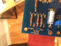
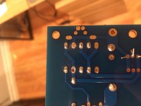
Here's the bit that was confusing me with the two holes, It should be linked somewhere.
I want to keep going but honestly the rational part of my brain is saying cut your losses and buy another set of PCBs and kit for $100 instead of playing Russian roulette with your speakers. Chalk it up as a learning experience or keep going? I have a LM3886 kit on order that should be easier and tie me over, right?
I cant get the picture over because my electronics decided to revolt but I think I got it figured out.
If you give the resistor designations according to the bill of materials it makes it easier to comment on your issue. If it is one of the extra filter resistor through holes you can just use another position for that resistor. These are all parallel if you look at the schematic, so the absolute position is not important.
Solder braid is very useful for removing that last annoying bit of solder after you've gotten most out with the pump.
Keep going, take it slow, but consider buying a second DMM as it will make the setup a lot easier. Build and use a mains light bulb limiter and get a set of cheapo crap speakers for the first connect.
It is nerve wracking the first time, but just be careful and the reward will make it all worth the trouble")
Solder braid is very useful for removing that last annoying bit of solder after you've gotten most out with the pump.
Keep going, take it slow, but consider buying a second DMM as it will make the setup a lot easier. Build and use a mains light bulb limiter and get a set of cheapo crap speakers for the first connect.
It is nerve wracking the first time, but just be careful and the reward will make it all worth the trouble
I second the suggestion of a second multimeter. It doesn't have to be a particularly
fancy one. Even something inexpensive from ebay or freight harbor will be useful.
Also, I recommend you print out the schematics and the BOM list, and
measure/verify every part before you populate it on the PCB. As you've noted,
it's really hard to tell the resistors apart by visual inspection.
If you're unsure about things, just ask. Lots of helpful folks here.
I have a cheap RadioShack plunger but for the life f me I just could not get the solder out, next time ill try to be more patient. All these Vishay resistors look identical and I'm afraid I might have mixed them up even though I really was trying to be careful. My inventory just isn't adding up for some reason. As far as the drilled hole, its for a non-essential resistor according to diyaudio store and "most builders wont need it". Should I just fill it with solder?
Here's the bit that was confusing me with the two holes, It should be linked somewhere.
I want to keep going but honestly the rational part of my brain is saying cut your losses and buy another set of PCBs and kit for $100 instead of playing Russian roulette with your speakers. Chalk it up as a learning experience or keep going? I have a LM3886 kit on order that should be easier and tie me over, right?
I cant get the picture over because my electronics decided to revolt but I think I got it figured out.
It's really hard to help you without pics. Please try to post some pics...could be a "no big deal" or it could be a "please put down the soldering iron" situation. I picture is literally worth a thousand words here.
Kevin.... totally agree, regarding "over the shoulder" help on this one.
Some useful tips:
To clear out a solder pad.... Warm up the solder in the pad until it flows. The take a round toothpick with a moistened end, and put it into the hole, rotating it a little in your fingers. Once the solder cools, you have a clean hole. It might not be open entirely, but it will permit you to reheat the pad, and then insert the new component's lead. This works very well if you have single pads you are working on. However, if you have a component with many leads (such as an op amp or other IC), I'd recommend the use of braid.
Do not drill out a pad, especially if it is through-plated. If the PCB has traces on both side, "clearing" a pad with a drill can ruin the connectivity of a through-plated pad.
Do yourself a favor. Find some old PCBs (from bad TVs, radios, etc) and practice your soldering and desoldering technique. No sense learning on your good F5 boards, unless you enjoy the financial impacts.
Do not overheat a pad, especially when removing a bad part. Although PCB manufacturing has become fairly indestructible over the years, it's still possible to lift the pad (and the circuit trace) from the board. You are using a relatively low-wattage soldering pencil, I would hope. Best yet, do you have a temperature-controlled soldering station?
As for parts. This might come too late for you, but before you start any construction, fully inventory your parts. Take a piece of typing paper or cardboard, and fasten the part to it.... from the BOM or schematic, write down the identifier (R1, R2, R3, C1, C2, etc) next to the part taped to the paper. In doing so, you'll be able to complete a thorough inventory, determine if you are missing any parts, and it will facilitate properly stuffing the board. This will be especially helpful if you are a DIY newbie.
I can't stress this enough, to save you time, money, and possible smoke..... Build the power supply first, and test it (read DC voltages), to confirm it is OK, BEFORE you connect any amp board to the supply.....
Best of luck. This might be a painful construction project for ya!
Okay! That's a lot of good advice there. I think the main problem with my soldering technique was that I was bending the leads before clipping and soldering them, to create a sort of hook, thought it would increase connectivity and made soldering easier for me. I just can't get it out now.
As far as inventory, I took inventory and measured every part individually before grouping them. I suspect I'm either freaking out over nothing and everything is fine, or I missed a little "k" when reading the resistance values. Doesn't help that the Vishay resistors are cryptic to me.
I'm using a soldering iron running at 40-45 watts.
I'm not sure what "lifting the pad" means but is it possible to fix it by using solder to complete the path?
Thank you, I realize I'm probably a poster child for what NOT to do when assembling electronics and I appreciate the patience. Gotta start somewhere right?uch:
I would be extremely grateful to anybody that could show me the ropes, nobody in my social circle or family knows this stuff. I generally learn best by jumping right in.
As far as inventory, I took inventory and measured every part individually before grouping them. I suspect I'm either freaking out over nothing and everything is fine, or I missed a little "k" when reading the resistance values. Doesn't help that the Vishay resistors are cryptic to me.
I'm using a soldering iron running at 40-45 watts.
I'm not sure what "lifting the pad" means but is it possible to fix it by using solder to complete the path?
Thank you, I realize I'm probably a poster child for what NOT to do when assembling electronics and I appreciate the patience. Gotta start somewhere right?
uch:I would be extremely grateful to anybody that could show me the ropes, nobody in my social circle or family knows this stuff. I generally learn best by jumping right in.
When desoldering stuff like resistors, the easiest way to do it cleanly is to clip the leads and then remove them while heating the pad. You lose the resistor but save the pcb.
As for resistance reading after soldering, the answer is “sometimes”... it really depends on the connections that resistor makes in the circuit.
As for resistance reading after soldering, the answer is “sometimes”... it really depends on the connections that resistor makes in the circuit.
R5 on the Pcb
OK Jake, there is good news and bad news.
Good news:
You didn't drill all the way through the pad (circular copper part connected to the trace). You probably will be OK soldering to what's left of the pad. Remember, a PCB is just a layer of thin, flat copper lines sandwiched in fiberglass. You can see the lines on the PCB. Once you solder a new resistor in your messed up hole you can check with a meter if it's connected to the next component down the line. Just follow the trace.
Your resistors have the resistance value printed right on them! Look at page 2 of this https://www.vishay.com/docs/31027/cmfmil.pdf check all your resistors, you should be fine. It's better to check them with a meter BEFORE you install them because once they are soldered in you can't measure the value because they may be effected by the other components.
The bad news:
Your soldering needs some help. It looks like your iron is either not hot enough or you are trying to apply the solder to soon. The joints should really look like round little mountains and shiny. You are not using enough solder as well. I'd find something to practice on before you move forward.
All in all your project is totally salvageable. Stay away from the drill press and keep asking questions and you will be fine.
Yes, you should reflow your solder joints.
I suspect that when you bent the lead to create the hook that it makes it
more difficult for the solder to flow on the pad and down the plated hole.
Some info on soldering can be found here:
Tools | Adafruit Guide To Excellent Soldering | Adafruit Learning System
Cheers,
Dennis
I suspect that when you bent the lead to create the hook that it makes it
more difficult for the solder to flow on the pad and down the plated hole.
Some info on soldering can be found here:
Tools | Adafruit Guide To Excellent Soldering | Adafruit Learning System
Cheers,
Dennis
- Status
- This old topic is closed. If you want to reopen this topic, contact a moderator using the "Report Post" button.
- Home
- Amplifiers
- Pass Labs
- First time F5 build