I plan to give some away at BAF....
")
Thanks Mr. Pass.
The amount of 2nd in the XA60.8's is miniscule compared to the amount
coming out of the Korg or H2.
BTW I have 200 of these little boards, and I am trying to find the time
to stuff some up for BAF.

If you need help in stuffing the boards for BAF, I’m happy to volunteer
my time and soldering skills.
If I can help, please send me a note.
Fooling with Psycho-Acoustics..easy!
My fascination with H2 continues unabated. The following is the experiment which Mark Johnson had suggested in an earlier post, and I later proposed to do per my above quote:
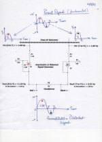
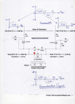
The attachment is a combination flowchart-schematic of the prototype build.
1. The top of the page shows a sine wave which is the Parent Signal or Fundamental. A peak value of [+1 Volt] is arbitrarily used for the positive-going segment spanning the real time of [0 to T] seconds. The negative segment of the AC signal spans the later time lapse of [T to T1] seconds. Its valley dip is [- 1 Volt]. My eardrums will oscillate exactly like the fundamental. The displacement or excursion of my eardrums are equal from [0 to T] as pushed in and pulled out during [T to T1] time. This is a symmetrical oscillation of my eardrums.
2. This AC signal [btw; it can also be triangular, saw tooth, square...any] is processed by a precision rectifier named a Class aP [analog Pulse] Generator.
3. This generator separates first [via rectification] the positive-going segment [0 to T] from the negative-going segment [T to T1]. It then aligns the direction of the resultant pulses to either be positive-going [as shown] or negative-going for independent processing using DC circuits.
The foolin' begins now
4. The parent red pulse [0 to T] of amplitude equal to +1.00 Vp is amplified by a non-inverter [U2] to a new height of + 1.18 Vp.
5. The parent black pulse [T to T1] of amplitude equal to + 1.00 Vp is attenuated in the non-inverting circuit of [U5] to a new [reduced] height equal to +0.91 Vp. Please note that I then normalized the resultant amplitudes.
6. The power output of the red amp [U2] is connected to the Red or + lead of the headphone. The output of the black amp [U5] is connected to the other Black or - lead of the headphone. May see it as a classical Class B operation.
7. The output of the Red amp [0 to T] moves the movable diaphragm of the headphone out or towards me or pushes air [raises pressure] in the ear canal against my eardrum; because this output current of [U2] is going in the [Red = +] lead of the phone. But note now the magnitude of the inward eardrum excursion or displacement which is proportional to the energy contained in the Red segment [0 to T] = +1.30.
8. At time [T to T1], the positive-going output pulse current of the Black amp [U5] enters the [Black = - ] lead of the headphone. It pushes in the diaphragm away from me or my ear drum and thus reduce air pressure in my ear canal. This partial vacuum in the time frame [T to T1] pulls out my eardrum to a normalized displacement equal to -1.00.
9. My ear has just experienced a Reconstituted or Distorted Fundamental; because of the different magnitude of the [in-out] displacement of my eardrum. My brain differentiates between the sound of the fundamental [equal displacement of ear drum] from that of the distorted fundamental.
10. Next reverse the leads of the headphone leads onto the output amps. This is equivalent to a 180 degree phase reversal of the resultant distorted signal. Or put a virtual mirror along the Time axis. The 180 degree reversed signal is the image therein.
11. The new situation is that my ear drum is pulled out [by partial vacuum] to a displacement of -1.30, during the [0 to T] time, and then pushed in [pressurization] to a displacement of +1.
12. My brain next sez: Antoun, I am glad to say that you don't and will fool me with your experiments/wizardry. You've heard 3 different sounds; that of the Fundamental, the distorted fundamental in bullet 9, and the distorted fundamental in bullets 10, 11.
13. What gives? The different peak to peak displacements of the ear drum, direction, and the resultant different physical, biochemical and electrical brain processes which followed inside the brain.
H2 is fun and entertainment. I also see it as a survival enhancement to recognize threats. I translate the impact of H2 positive phase " in one's face" per the teaching of Mr. Pass as the threat ; say from a grizzly is coming at you. By contrast H2 phase negative as this same threat is moving away or "receding". Can't outrun a grizzly. Taser it first and then run.
Best
Anton
Hi Mark Johnson. Your above suggestions can be readily implemented by using Class aP amplification as follows:
1. Precision rectify the AC signal to get separate positive and negative pulses.
2. Pulses of either polarity can now be processed independently by DC amplifiers.
3. For example; the positive going pulse is amplified by a gain factor of two and the resultant summed with the intact negative pulse.
In your earlier post# ~190, you also discussed the subject regarding push-pull amplification. Class aP amplification is actually Class B;, but with a broader flexibility [and needed complexity] to fuss at will with distortion as you taught.
I will dust-off my one-of-kind stereo "precision aP generator" and explore experiments. A picture of it and its schematic are therein the thread.
best
Anton
My fascination with H2 continues unabated. The following is the experiment which Mark Johnson had suggested in an earlier post, and I later proposed to do per my above quote:
The attachment is a combination flowchart-schematic of the prototype build.
1. The top of the page shows a sine wave which is the Parent Signal or Fundamental. A peak value of [+1 Volt] is arbitrarily used for the positive-going segment spanning the real time of [0 to T] seconds. The negative segment of the AC signal spans the later time lapse of [T to T1] seconds. Its valley dip is [- 1 Volt]. My eardrums will oscillate exactly like the fundamental. The displacement or excursion of my eardrums are equal from [0 to T] as pushed in and pulled out during [T to T1] time. This is a symmetrical oscillation of my eardrums.
2. This AC signal [btw; it can also be triangular, saw tooth, square...any] is processed by a precision rectifier named a Class aP [analog Pulse] Generator.
3. This generator separates first [via rectification] the positive-going segment [0 to T] from the negative-going segment [T to T1]. It then aligns the direction of the resultant pulses to either be positive-going [as shown] or negative-going for independent processing using DC circuits.
The foolin' begins now
4. The parent red pulse [0 to T] of amplitude equal to +1.00 Vp is amplified by a non-inverter [U2] to a new height of + 1.18 Vp.
5. The parent black pulse [T to T1] of amplitude equal to + 1.00 Vp is attenuated in the non-inverting circuit of [U5] to a new [reduced] height equal to +0.91 Vp. Please note that I then normalized the resultant amplitudes.
6. The power output of the red amp [U2] is connected to the Red or + lead of the headphone. The output of the black amp [U5] is connected to the other Black or - lead of the headphone. May see it as a classical Class B operation.
7. The output of the Red amp [0 to T] moves the movable diaphragm of the headphone out or towards me or pushes air [raises pressure] in the ear canal against my eardrum; because this output current of [U2] is going in the [Red = +] lead of the phone. But note now the magnitude of the inward eardrum excursion or displacement which is proportional to the energy contained in the Red segment [0 to T] = +1.30.
8. At time [T to T1], the positive-going output pulse current of the Black amp [U5] enters the [Black = - ] lead of the headphone. It pushes in the diaphragm away from me or my ear drum and thus reduce air pressure in my ear canal. This partial vacuum in the time frame [T to T1] pulls out my eardrum to a normalized displacement equal to -1.00.
9. My ear has just experienced a Reconstituted or Distorted Fundamental; because of the different magnitude of the [in-out] displacement of my eardrum. My brain differentiates between the sound of the fundamental [equal displacement of ear drum] from that of the distorted fundamental.
10. Next reverse the leads of the headphone leads onto the output amps. This is equivalent to a 180 degree phase reversal of the resultant distorted signal. Or put a virtual mirror along the Time axis. The 180 degree reversed signal is the image therein.
11. The new situation is that my ear drum is pulled out [by partial vacuum] to a displacement of -1.30, during the [0 to T] time, and then pushed in [pressurization] to a displacement of +1.
12. My brain next sez: Antoun, I am glad to say that you don't and will fool me with your experiments/wizardry. You've heard 3 different sounds; that of the Fundamental, the distorted fundamental in bullet 9, and the distorted fundamental in bullets 10, 11.
13. What gives? The different peak to peak displacements of the ear drum, direction, and the resultant different physical, biochemical and electrical brain processes which followed inside the brain.
H2 is fun and entertainment. I also see it as a survival enhancement to recognize threats. I translate the impact of H2 positive phase " in one's face" per the teaching of Mr. Pass as the threat ; say from a grizzly is coming at you. By contrast H2 phase negative as this same threat is moving away or "receding". Can't outrun a grizzly. Taser it first and then run.
Best
Anton
Attachments
My fascination with H2 continues unabated. The following is the experiment which Mark Johnson had suggested in an earlier post, and I later proposed to do per my above quote:
The attachment is a combination flowchart-schematic of the prototype build.
1. The top of the page shows a sine wave which is the Parent Signal or Fundamental. A peak value of [+1 Volt] is arbitrarily used for the positive-going segment spanning the real time of [0 to T] seconds. The negative segment of the AC signal spans the later time lapse of [T to T1] seconds. Its valley dip is [- 1 Volt]. My eardrums will oscillate exactly like the fundamental. The displacement or excursion of my eardrums are equal from [0 to T] as pushed in and pulled out during [T to T1] time. This is a symmetrical oscillation of my eardrums.
2. This AC signal [btw; it can also be triangular, saw tooth, square...any] is processed by a precision rectifier named a Class aP [analog Pulse] Generator.
3. This generator separates first [via rectification] the positive-going segment [0 to T] from the negative-going segment [T to T1]. It then aligns the direction of the resultant pulses to either be positive-going [as shown] or negative-going for independent processing using DC circuits.
The foolin' begins now
4. The parent red pulse [0 to T] of amplitude equal to +1.00 Vp is amplified by a non-inverter [U2] to a new height of + 1.18 Vp.
5. The parent black pulse [T to T1] of amplitude equal to + 1.00 Vp is attenuated in the non-inverting circuit of [U5] to a new [reduced] height equal to +0.91 Vp. Please note that I then normalized the resultant amplitudes.
6. The power output of the red amp [U2] is connected to the Red or + lead of the headphone. The output of the black amp [U5] is connected to the other Black or - lead of the headphone. May see it as a classical Class B operation.
7. The output of the Red amp [0 to T] moves the movable diaphragm of the headphone out or towards me or pushes air [raises pressure] in the ear canal against my eardrum; because this output current of [U2] is going in the [Red = +] lead of the phone. But note now the magnitude of the inward eardrum excursion or displacement which is proportional to the energy contained in the Red segment [0 to T] = +1.30.
8. At time [T to T1], the positive-going output pulse current of the Black amp [U5] enters the [Black = - ] lead of the headphone. It pushes in the diaphragm away from me or my ear drum and thus reduce air pressure in my ear canal. This partial vacuum in the time frame [T to T1] pulls out my eardrum to a normalized displacement equal to -1.00.
9. My ear has just experienced a Reconstituted or Distorted Fundamental; because of the different magnitude of the [in-out] displacement of my eardrum. My brain differentiates between the sound of the fundamental [equal displacement of ear drum] from that of the distorted fundamental.
10. Next reverse the leads of the headphone leads onto the output amps. This is equivalent to a 180 degree phase reversal of the resultant distorted signal. Or put a virtual mirror along the Time axis. The 180 degree reversed signal is the image therein.
11. The new situation is that my ear drum is pulled out [by partial vacuum] to a displacement of -1.30, during the [0 to T] time, and then pushed in [pressurization] to a displacement of +1.
12. My brain next sez: Antoun, I am glad to say that you don't and will fool me with your experiments/wizardry. You've heard 3 different sounds; that of the Fundamental, the distorted fundamental in bullet 9, and the distorted fundamental in bullets 10, 11.
13. What gives? The different peak to peak displacements of the ear drum, direction, and the resultant different physical, biochemical and electrical brain processes which followed inside the brain.
H2 is fun and entertainment. I also see it as a survival enhancement to recognize threats. I translate the impact of H2 positive phase " in one's face" per the teaching of Mr. Pass as the threat ; say from a grizzly is coming at you. By contrast H2 phase negative as this same threat is moving away or "receding". Can't outrun a grizzly. Taser it first and then run.
Best
Anton
I would like to know how technically the stability of the asymmetry in the gain (close to 1%) would be guaranteed, both in time and frequency, waiting for the offset action. How would you avoid the consequences of zero crossing?
#13 is somewhat along the lines of my own speculation with regards
to Doppler approaching vs receding.
In any case, send me your address and I will save you a trip to BAF.
Thanks Mr. Pass for your never-ending generosity of knowledge, and the offer of H2.
I am looking at the envelope post-marked Jan. 19, 2017; which you've sent me containing two [gratis] SemiSouth SJDP120R085; to experiment with DEF.
I'll send you a letter to the address on it.
Best
Anton
I would like to know how technically the stability of the asymmetry in the gain (close to 1%) would be guaranteed, both in time and frequency, waiting for the offset action. How would you avoid the consequences of zero crossing?
Hello diegomj1973.
Thanks for you post. I hope that I understand your technical concerns:
1. Class aP amplification was meant to avoid the consequences of zero crossing [X-over distortion]; before its two independent[line level] signals go to the power output stage.
2. But; I believe there is more to your valid concern. The headphone [in my schematic] is a coil of a certain inductance which also has resistance.
3. The asymmetric drive I showed at the bottom of the schematic is expected to generate two different back EMFs or magnetic storage; which must be dissipated quickly.
4. Not shown in the schematic is a 1K resistor which I put across the headphone. It removed the garbage sounds of the asymmetric back EMFs to give a crystal clear reproduction of the asymmetric music signals.
5. I will find the limits of this asymmetry. How extensive can I push it, and still be fully acceptable to my hearing.
Best
Anton
Pushing the envelope
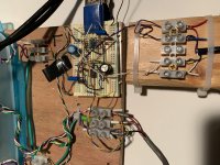
The attached picture is the evolving [incremental tweaks] prototype under study.
1 The blue Tupperware on the left of the view encloses the Class aP Generator. Please peruse Post #200 in the thread 'Class aP amplification" which you'll find in the Pass Labs Forum.
2. The resultant Asymmetric or Distorted Signal Generator is seen on the prototyping-board. Any post's ability to magnify an attached picture is truly an enhancement to follow the schematic.
3. The European connector on the [2 by 4] piece of wood interfaces the Grado SR80 headphones to the prototyping board. Note that I had clipped-off Grado's standard factory plug, and then separated the Right channel's [hot-cold] leads from the Left channel [hot-cold] leads. Thus; the L and R phones no longer share a common ground. Bad idea to clip the headphones plug? Hell no. The plug was/is a great barrier to experimenting therein this study and others!
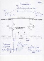
The combination signals' flow-chart/schematic shows new details. This pertains to the prototype which I currently use to listen to its music.
1. Caricature depictions of the two resultant distorted signals . As generated and its inverted one via reversing the [hot-cold] leads of the phones.
2. Pushed the distortion "envelope". A new normalized ratio equal to [1.4 to 1 ] in favor of the time segment [0 to T ] seconds.
3. A Zobel [10 Ohm in series with a 0.15uF film cap] put across the load. My poor layout on the prototyping board may have stimulated the wide bandwidth OpAmp [ RC4560] to misbehave, and generate unprovoked hash.
4. An algebraic equation which calculates % H2 distortion from the normalized data as follows:
% H2 [either phase] = 0.4 [equivalent area expansion] divided by 2.4 [ the total area of the resultant signal] multiplied by 100 [for percent] and lastly divided by 2 [it is H2 afterall]. The answer is 8.3%. Wild? Compare with the accurate [FT] number which I do not know how to do.
Hint: Use Mr. Mark Johnson's simulation values in a previous post: [ 0.5/ 2.5] X [100/2] = 10% versus 11%.
Last but not least, the resultant two distorted signals do not sound the same. The color coded leads for each phone [in the picture...magnify and track] show that my hearing favored the sound of the inverted music. Ditto for this current version of the prototype.
Hi-Fi sound? No way by the established definitions of Hi-Fi. Frankly Antoun, I don't give a damn sez by brain; you do like the music I gave you to hear via the above gizmo.
Best
Anton
The attached picture is the evolving [incremental tweaks] prototype under study.
1 The blue Tupperware on the left of the view encloses the Class aP Generator. Please peruse Post #200 in the thread 'Class aP amplification" which you'll find in the Pass Labs Forum.
2. The resultant Asymmetric or Distorted Signal Generator is seen on the prototyping-board. Any post's ability to magnify an attached picture is truly an enhancement to follow the schematic.
3. The European connector on the [2 by 4] piece of wood interfaces the Grado SR80 headphones to the prototyping board. Note that I had clipped-off Grado's standard factory plug, and then separated the Right channel's [hot-cold] leads from the Left channel [hot-cold] leads. Thus; the L and R phones no longer share a common ground. Bad idea to clip the headphones plug? Hell no. The plug was/is a great barrier to experimenting therein this study and others!
The combination signals' flow-chart/schematic shows new details. This pertains to the prototype which I currently use to listen to its music.
1. Caricature depictions of the two resultant distorted signals . As generated and its inverted one via reversing the [hot-cold] leads of the phones.
2. Pushed the distortion "envelope". A new normalized ratio equal to [1.4 to 1 ] in favor of the time segment [0 to T ] seconds.
3. A Zobel [10 Ohm in series with a 0.15uF film cap] put across the load. My poor layout on the prototyping board may have stimulated the wide bandwidth OpAmp [ RC4560] to misbehave, and generate unprovoked hash.
4. An algebraic equation which calculates % H2 distortion from the normalized data as follows:
% H2 [either phase] = 0.4 [equivalent area expansion] divided by 2.4 [ the total area of the resultant signal] multiplied by 100 [for percent] and lastly divided by 2 [it is H2 afterall]. The answer is 8.3%. Wild? Compare with the accurate [FT] number which I do not know how to do.
Hint: Use Mr. Mark Johnson's simulation values in a previous post: [ 0.5/ 2.5] X [100/2] = 10% versus 11%.
Last but not least, the resultant two distorted signals do not sound the same. The color coded leads for each phone [in the picture...magnify and track] show that my hearing favored the sound of the inverted music. Ditto for this current version of the prototype.
Hi-Fi sound? No way by the established definitions of Hi-Fi. Frankly Antoun, I don't give a damn sez by brain; you do like the music I gave you to hear via the above gizmo.
Best
Anton
Attachments
Another view of H2..
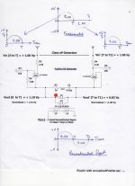
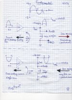
Four new changes are in the attached flow-chart/schematics of the positive and negative phase H2 Harmonic Generators.
1. The overall phase of the Fundamental and Reconstituted signals are the same [a must]. The resultant flow of action from the input electrical signal to its resultant sound pressure destination [eardrum] is the same for all 3 signals.
2. I normalized the valley depth to [-1] for the [T to T1] segment of the 3 different signals. This clearly exposes [only] the relative state of the eardrum during the [0 to T] segment of the 3 different signals. It is the objective.
3. A Jensen transformer[the one in diyF6] was used to reconstruct the resultant harmonius signals. The resultant signals at the secondary winding of the transformer are the inputs to Class T amp or other.
4. A substantial dose of harmonics was introduced in the Fundamental.
a. A positive phase signal was enriched with 9% H2 per my crude calculation in the previous post. Add to it the residual stragglers of higher harmonics which could give a total of say 12% THD.
b. I calculate an unbelievable 21% H2 negative phase to up to 25% %THD.
I hope diyAudio students of Fourier can use the available data;[meaning the values of Vpeak during the [0 to T] segments to recalculate with absolute accuracy.
The left flow-chart/schematic generates H2 positive phase [H2pp] . Slide [mentally] the Reconstructed signal exactly on top of the original Fundamental signal [both are in phase]. The resultant action of [H2pp] during the [0 to T] segment is to move-in the eardrum to a deeper displacement than from the Fundamental.
The right flow-chart/schematic generates H2 negative phase [H2np] . Mentally slide the Reconstructed signal atop the Fundamental. The resultant inward displacement of the eardrum is less than the Fundamental's during the [0 to T] segment.
Overlay the Fundamental [H2pp] and, [H2np] signals on top of each other. The resultant view during the [0 to T] segment shows their relative effect on the movement of the eardrum. This is an answer and or explanation.
But; how does the three signal variations sound via headphones and loudspeaker? I was surprised as you are now. Great and this is not an overstatement.
Attachments
[...]
But; how does the three signal variations sound via headphones and loudspeaker? I was surprised as you are now. Great and this is not an overstatement.
Hard to understand all, and evaluate, lacking of pratice, experience, and knowledge, but not of curiosity... if i want to experiment :
1. i have to build the shematic from class aP post #200
3.Bias diode as shown in post #208 of class aP thread => i don't understand the constant source shematic variation in connection to ground between this one and the one of post 200...wich one do i do ?
4.Choose and build one of the H2 generator shematics here
5.connect outputs of buffers of class aP generator, before their 1k resitors, to the inputs of H2 generator
6. send directly the jensen output to a amp, and that's all ?
We are on pins and needles.
By comparison, I am dancing barefoot on hot embers waiting patiently for an H2 Harmonic Generator [H2HG]; gratis from you. [H2HG] is a precious catch/find to me and hopefully to more others . I will treasure it simple engineering and sonic value. Because my experiments with [H2] have already given me an in-depth understanding of your article and an appreciation of its sonic consequence.
Best
Anton
Hard to understand all, and evaluate, lacking of pratice, experience, and knowledge, but not of curiosity... if i want to experiment :
1. i have to build the shematic from class aP post #200
3.Bias diode as shown in post #208 of class aP thread => i don't understand the constant source shematic variation in connection to ground between this one and the one of post 200...wich one do i do ?
4.Choose and build one of the H2 generator shematics here
5.connect outputs of buffers of class aP generator, before their 1k resitors, to the inputs of H2 generator
6. send directly the jensen output to a amp, and that's all ?
Hello papasteack,
Thanks for your post. May I suggest:
1 Experiment first with the H2 Harmonic Generator [H2HG] by Mr. Pass. It is absolutely simple. It already has the electrical connection points for the original music, and the resultant music enriched with either H2 negative phase [H2np] or H2 positive phase [H2pp]. By using small switching relays you will be able to compare the subjective sound from the 3 different signals. I hope that you already have a good understanding of the article by Mr. Pass on [H2HG].
2. My experiments and their prototypes are complicated; but detailed. I can experiment at will because I have the time and the practical tools; like the Class aP Generator which I assembled several years ago. That came from a long study!
3. Still, my experiments and prototypes are easy to assemble on prototype board like I show; that if you choose to as you wrote in your post above.
Best
Anton
Mr. Pass asked: Why do we care about 2nd harmonic? in the Introduction of his article entitled H2 Harmonic Generator. A commensurate answer is it triggers emotions.
Music containing H2 negative phase [H2np] flares up emotions [literally]. This resultant affect is potent and also reproducible in my subjective experience. Follow this suggestion should you wish to experiment:
1. Use the H2 Harmonic Generator [H2HG] by Mr. Pass.
2. Buffer its outputs so as to drive headphones.
3. The Fundamental music input to [H2HG] is the headphones outputs of a typical laptop. A Class D mini amp is most likely the music generator.
4. I listen to music videos on YouTube which unravels the magic of [H2np].
4a. My music has emotional meaning, and goes back to 1965. Lots of emotions tethered to it in this long tunnel of time.
4b. Music videos engage my sight and sound senses. I also close my eyes as a blank [blind] experience .
4c. I sing along or at best I try to. Singing is an emotional experience. Note the new acoustic feedback [pristine I just added to my ears. Alexa and other gizmos like it can now speak and sing "with any affect of emotions".
Fun and entertainment. Hold on to your [H2HG].
Best
Anton
Can a loudspeaker emulate H2?
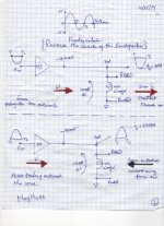
Hypothesis?. Here is my argument. The left attachment shows the following:
1. The Fundamental [Fun; ain't it?] music signal is at its top.
2. The [Fun] input signal is [Vin] to a non-inverting power amp [PA]. [PA] has an intrinsic output DC Offset equal [-40 mV]. This DC offset and its consequences are the variables under study. The blank for this experiment is a DC offset = 0.00 V.
3. A loudspeaker load to [PA] with focus on the connections of its [Red = +] lead to the output of [PA]. The woofer is normally DC-coupled to the power output and is shown to have a resistance of 4 Ohms.
It follows that the [-40 mV] offset drive to the woofer's coil has two consequences:
a. Ground sources a [10 mA] curent which passes through the woofer coil and is sunk by [PA]. This current creates an electromagnet and a resultants force [F]; black arrow which pulls inward the woofer cone. This [F] is small.
b. The woofer coil dissipates heat equal to [0.4 mW].
In operation, the positive-going segment of [Vin] during its allocated time [0 to T], allows [PA] to source a positive current [0.707 A] through the the 4 Ohm load to ground. The resultant "dynamic electromagnet" generates a force [red arrow] which pushes outwards the woofer cone. This results in a positive-going air pressure coming at my ears. But; the outward pushing force [a vector] is opposed or hindered by the inward pulling force [F] from the static electromagnet.
During the negative-going segment of [Vin], the resultant motion of the woofer cone is reversed. It is pulled inward away from me and is aided by [F] which is acting in the same direction.
My bold language above reads like the description by Mr. Pass for the synthesis of H2 negative phase [H2np]. . It suggests the synthesis or emulation of H2np via this third "magnetic route".
.
Let's reverse the loudspeaker leads so as to unravel the consequences. The graphics are shown in the right attachment. But note:
a. The weak force [F; now color red] is pushing outward the cone of the woofer.
b. I shifted the time of the negative-going segment of [Vin] to [T to T1]. So as to result in the outward motion of the woofer cone; like in the previous case. Essentially it is a clean comparison of "apples to apples"; especially for the resultant and same directional movement of my ear drum.
It follows that force [F] aides the outward motion of the woofer cone and opposes it during its inward motion. This language is like that used by Mr. Pass to explain H2 positive phase[H2pp].
Think about the consequences of a DC offset equal [-200 mV]; or even higher. The resultant idle current is 50 mA and generates a larger force [F]. The heat dissipated in the voice coil rises to 10 mW.
What is the DC offset at the output of your power amp? Will you tell a "subjective" difference in the music when the loudspeaker leads are reversed? The above suggests hearing a fundamental enriched with H2np versus one with H2pp.
Best
Anton
Attachments
.You will be interested in experiments I did with cone loudspeakers and DC offset,
where I was able to either cancel H2 in a speaker or generate H2 of either phase
with DC. Easy to do, and you can generally take it up to a volt or so without
damaging anything.
Thanks Mr. Pass for your note. It is loaded with valuable knowledge. I [and hopefully other DIYers] will be glad to read about your pioneer experiments.
I listen via Grado headphones [32 Ohms per side] to a mini amp [MA]. [MA] puts an adjustable DC offset across each phone in the range of -35 mV to + 35 mV. The resultant [~ 1 mA] generates a heat dissipation in the phone's voice coil of 0.032 mW.
But; the subjective sound at -35 mV offset is different from that due to +35 mV; like the different subjective impressions you've already reported.
I am glad to learn that the music drivers are agreeable [within limits] to have and generate asymmetric performance. More future experiments.
Best
Anton
OK everybody, listen up:
FIRST WATT
Revised H2 generator kit article.
Makes for a nice preamp.
I have 200 of these kits all packed up, and I'm taking a lot of them
to BAF this next weekend.
FIRST WATT
Revised H2 generator kit article.
Makes for a nice preamp.
I have 200 of these kits all packed up, and I'm taking a lot of them
to BAF this next weekend.