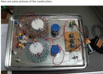
I am talking about the schematic to build a notch filter to transform an oscilloscope into a distortion analyser. It is to display the waveform of the distortion like pass is doing in his writing.
This permits to determine the polarity of H2 etc etc
it is not a spectrum analyser that gives only the intensity of H2 and H3
This permits to determine the polarity of H2 etc etc
it is not a spectrum analyser that gives only the intensity of H2 and H3
Maybe you would want to consider a circuit where the inverter is
optionally on the input side or output side. Picking one versus the other
allows listening to + phase second harmonic or - phase.
Mr. Pass, any comments or thoughts on using the common drain version of the amp to get a non-inverting signal?
Like used in the schematics in my post (#123)
https://www.diyaudio.com/forums/pass-labs/327746-h2-3.html#post5592238
Thanks
")
The package is called TO92.
Here is a link to the data sheet.
See page 3.
http://www.ti.com/lit/ds/symlink/lm317l-n.pdf
Thanks, Doug. Would not have known that LM317 comes in various package configurations.
Have ordered mini displays
<5PCS Mini Blue DC 0-30V LED Panel Voltmeter 3-Digital Display Voltage Meter 708624425963 | eBay
It was indicated that the display should be attached between V+ of the LM317 and GND but display has 3 leads. Which leads go to where?
Signed NEWB
Try Dick Moore's Active Twin-T notch filter.... it seems this can be done with a scope and a notch filter to remove the 1Khz fundamental tone
is there any schema that I could use?
Attachments
In the past you have referred to in phase and out of phase H2. Could you please
clarify whether in phase H2 is what you refer to as the negative phase
H2 or is it vice versa?
I know it tends to be confusing.
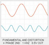
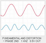
Positive phase 2nd is when the distortion waveform has a positive peak
at the same time that the fundamental has a peak, positive or negative.
Negative phase 2nd is when it has a negative peak. I have attached
two scope photos showing the fundamental aligned with the distortion.
Additionally, we have to consider the absolute phase of the audio signal -
if you invert the phase, positive phase 2nd becomes negative, and
vice versa.
The result is that if your harmonic generator inverts phase as this one
does, you have to change the absolute signal phase either before or
after to correct this.
If you invert the signal before the generator, then the 2nd harmonic of
the generator goes to the speaker unchanged. If you change the phase
after the generator, the 2nd harmonic is flipped as well, so it has the
opposite phase distortion.
For this circuit, I got the best 2nd harmonic with a +phase, and then
we invert the signal after the generator to get correct absolute phase
with a -phase second harmonic.
One can adjust the generator to get either. As you adjust the V+ of
the supply, you can lower the +phase 2nd harmonic until it is nulled
out, leaving the 3rd harmonic, as as you go further, you get a -phase
2nd. I found that the +phase region gave the better maximum output
voltage and also a slightly purer 2nd. Also, it makes for easy use since
you only need to change the speaker polarity to get absolute phase
correct.
Attachments
oh yes
Greedy Boyz are greedy , by definition

At least I am not asking for a SiT H2

Is it possible to build a "double inverter" so we could have a switch at the front, then we could do a fast switching of the phase, in case we don't want to mess with speaker connections, or if we want to quickly switch the phases, to compare the effects?
Certainly it's possible. If you don't like relays you can implement it with a good old fashioned 3PDT switch. One section of the switch selects which signal is applied to the input of the H2 generator. A second section of the switch selects which signal is applied to the input of the gain-of-minus-one inverter. A third section of the switch selects which signal routed to the output of the switchbox. So that's 3PDT.
Mouser sells this one for less than five dollars.
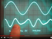
Try Dick Moore's Active Twin-T notch filter.
using this Active Twin-T notch filter between amp and scope will I have the nice distortion trace on the scope (the bottom one in the video or in pass pictures) ?
Or do I need a more complex distortion meter with a specific output for that? (mentioned in the video)
I found this little figure in the Jan 2019 issue of Stereophile. It's part of the measurements section, in a review of a tube power amp.
Anybody want to positively state with confidence and complete certainty, whether this tube amp produces "positive phase" or "negative phase" distortion? And whether the distortion is H1, H2, H3, or something else?
_
Anybody want to positively state with confidence and complete certainty, whether this tube amp produces "positive phase" or "negative phase" distortion? And whether the distortion is H1, H2, H3, or something else?
_
Attachments
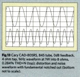
Negative phase H2

I agree! When using LTSpice and viewing the harmonic distortion components the 2nd harmonic will be +45 degrees relative to the fundamental for a perfect neg. phase 2nd harmonic.I've used this method for tuning my F7 approximation and my ears like that setting more than all the others I have tried.
Last edited:
The ACA produces a positive phase 2nd harmonic. The speaker connections are inverted with the + speaker lead grounded. It squishes the top part of the waveform at the output. I verified this with an X-Y plot of the ACA output in the ACA thread.
Would an ACA built with P channel FETs produce a negative phase 2nd harmonic at the output ? Would you still need to invert the speaker connections ? Would this be better for head phones because of the common ground on the sleeve of the stereo phone plug ?
Would an ACA built with P channel FETs produce a negative phase 2nd harmonic at the output ? Would you still need to invert the speaker connections ? Would this be better for head phones because of the common ground on the sleeve of the stereo phone plug ?
The ACA is inverting for both N and P channel FET. Speaker polarity connection is reversed (+ to ground) to maintain absolute phase in any case. Input to the ACA needs to be inverte to get both correct absolute phase and negative H2 from non inverted speaker connection. There are several ways to do that: a polarity plugin for foobar, an inverting preamp like the jBOZ, an 600 or 10k line matching transformer used with the output inverted and many others.