Last edited:
Nelson also talks about it in this thread:
Sound of various Pass amps
Sound of various Pass amps
SIT-1: Broke the mold in the ability to play with the load line of a no-feedback
Common Source amplifier that still has any damping factor. A very unique
harmonic signature that can be dialed in to taste - Lots or little of 2nd
harmonic of either phase. Literally the sound of one transistor clapping -
without the input buffer (which no one seems to use) there is only 1
transistor in the amp. Has tremendous clarity and depth, depending on
setting, spectral consistency with warmth and detail. It allows you to focus
on a single instrument in an ensemble, almost to the exclusion of all else if
you want. This is the amp that convinced me that absolute phase is not
such a subtle factor.
SIT-2: A SIT-1 with a constant current source load instead of a stack of
power resistors. More efficient but similar to the SIT-1, it is set at a single
load line setting, so is not quite as flexible or fun.
can it be used as preamp with very high input impedance and again of around 10db by changing the registers :
R1 = around 150K or 160K
R3 = 39K
Then i think the input impedance will be around 150k.. is my understanding ok?
Can we increase the input impedance to around 1Mohms?
Also does it needs a output buffer to lower output impedance when used as a preamp with gain.
R1 = around 150K or 160K
R3 = 39K
Then i think the input impedance will be around 150k.. is my understanding ok?
Can we increase the input impedance to around 1Mohms?
Also does it needs a output buffer to lower output impedance when used as a preamp with gain.
Last edited:
...SIT-2: A SIT-1 with a constant current source load instead of a stack of
power resistors. More efficient but similar to the SIT-1, it is set at a single
load line setting, so is not quite as flexible or fun...

Well, my SIT-2 is the most fun I've ever had with an amplifier!
I posted this schematic in another thread because I was clueless & did not realize this thread exists.
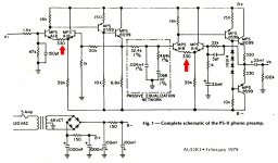
It came from a review of a phonostage in Audio Magazine, February 1979. Sold by a company that's still in business today.
Each of the two Long Tailed Pairs is intentionally unbalanced, by adding an emitter degeneration resistor (330 ohms) to only one of the two legs of the Long Tailed Pair. This creates 2nd order harmonic distortion and apparently that was a design goal. Somebody knew something, long long ago.
I like to analyze the circuit this way: Imagine that the 330 ohm resistor is really a 3-terminal device, a potentiometer. Its wiper connects to the 39K bias resistor, and its outer arms connect to the two emitters. With the wiper at the midpoint (165 ohms left, wiper, 165 ohms right), the circuit is balanced. However the designer has intentionally chosen to turn the pot all the way clockwise, and now it's (330 ohms left, wiper, 0 ohms right). The circuit is no longer balanced.
If you built the circuit and used an actual potentiometer, you could seamlessly dial from lots of positive phase H2, to nearly-zero, to lots of negative phase H2, just by twirling the dial. And, get this, you could have done so 40 years ago! I bet it was designed in 1978 or perhaps 1977, took a few months to build production units, shipped one to an Audio Magazine reviewer, who took a few months to do the review and write his article, turned in his copy, which took a few months to get typesetted and appear in print, in Feb 1979.
By the way, do a google image search for the schematic of the B&K ST140 power amp (mid 1980s), an early lateral-MOSFET amp widely praised for its smooth sound. What do you see? Cowabunga!!
_
Attachments
Last edited:
Although seemingly counterintuitive, I believe/recall that the ‘unbalanced’ resistors actually aids symmetry in the complete circuit ... I’ll give this a twirl on a Sim to make sure my memory isn’t playing tricks on me ...
Does your memory tell you that having two 330 ohm resistors in place, as shown, is in some way better than having zero 330 ohm resistors, and also better than having one 330 ohm resistor? That would surprise me.
Earlier this year Bob Katz wrote an article about a device he built called "Bobs Blender". He could introduce 2nd harmonic into a signal path with it. He used tubes and in fig 5 of the link below it shows only second harmonic, no third or higher order products. The article on the Pass H2 shows some third and fourth harmonic.
Is this because JFETs are square law devices while tubes are Childs law devices?
Katz's Corner Episode 25: Adventures in Distortion | InnerFidelity
Is this because JFETs are square law devices while tubes are Childs law devices?
Katz's Corner Episode 25: Adventures in Distortion | InnerFidelity
I would say the tube is more nearly square law.
That said, if you bias the J112 for "positive phase 2nd" you get a cleaner
2nd harmonic, but more limited maximum output.
Clearly this circuit can be improved, but I popped this out for free fun
giveaway at BAF. Not as an example of the best possible.
That said, if you bias the J112 for "positive phase 2nd" you get a cleaner
2nd harmonic, but more limited maximum output.
Clearly this circuit can be improved, but I popped this out for free fun
giveaway at BAF. Not as an example of the best possible.
I would say the tube is more nearly square law.
That said, if you bias the J112 for "positive phase 2nd" you get a cleaner
2nd harmonic, but more limited maximum output.
Clearly this circuit can be improved, but I popped this out for free fun
giveaway at BAF. Not as an example of the best possible.
Thanks for the reply Nelson, and thank you for giving all of us this circuit.
The "Danyuk Resistor" calculated to be 63 Ohms for the J112 JFET I was using. The graphs below depict THD for different values of Vss with and without degeneration. Plot #5 on each graph is where H2 canceled. Very touchy to adjust the lab power supply to find the null. At lower values of Vss, the H2 phase is positive, at higher values, H2 phase is negative if I understand the article.
The whole business of phase of H2 and the inverting nature of the H2 generator is still confusing. See the third attachment. You turn the picture upside down and the phase still looks positive.
It's important to note that this circuit actually generates a positive phase 2nd harmonic, but after you invert the output (to get absolute phase correct) you will find that it is now a negative phase 2nd harmonic. I know this might be confusing – I have occasionally awakened in the middle of the night and thought “That can't be right.” But it is, and if you turn the above pictures upside down you should see it.
The whole business of phase of H2 and the inverting nature of the H2 generator is still confusing. See the third attachment. You turn the picture upside down and the phase still looks positive.
Attachments
LTSpice Distortion Spectra of FW H2, 2SK79 SIT and 6922
Surprisingly similar simulated distortion signature from schaded J112 , 2SK79 SIT and 6922 triode.
Surprisingly similar simulated distortion signature from schaded J112 , 2SK79 SIT and 6922 triode.
Attachments
WOW!
Please forgive the 400V supply and 15W dissipation on drain load resistor. Welcome to the world no triode has gone before.
Please note what Papa said in the paper: "Speaking of that, this circuit has a substantial turn-on and turn-off thump, ...". This one has a fantastic turn-on and turn-off BOOM!!!, output protector is mandatory. Beware, you have been warned.
Attachments
Last edited:
The whole business of phase of H2 and the inverting nature of the H2 generator is still confusing. See the third attachment. You turn the picture upside down and the phase still looks positive.
You are looking at the wrong spot. At the point where the red fundamental
is positive, you will see that the blue is negative. Same for when the red is
peaking negative.
I know that it tends to be confusing.....
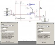
This is my very humble contribution. As I do not physically have transistor J112 to experiment with it and the model used by the Multisim 14 simulator does not work for virtual evaluation, I started experimenting with another non-feedback circuit that works with intense signals, but reaches a similar distortion profile than the one suggested by Mr. Nelson Pass.
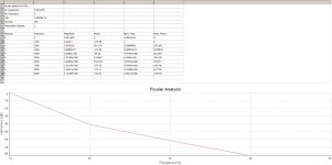
With this circuit, I will run a virtual evaluation using simultaneously Multisim 14 and useful LabView tools. The idea is to inject a file fragment in the .wav format into the test circuit, so that its maximum amplitude tends to make the circuit work at a point close to that proposed by Mr. Nelson Pass. This point would be the one that causes a distortion with a profile defined between H2, H3 and H4 like the one that can be seen in the following figure. It corresponds to a THD of around 0.9% and is given for an input signal of 0.5 V peak.

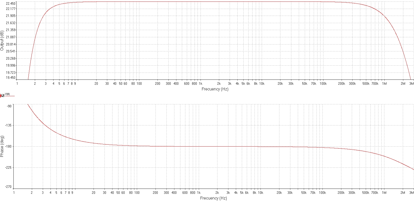

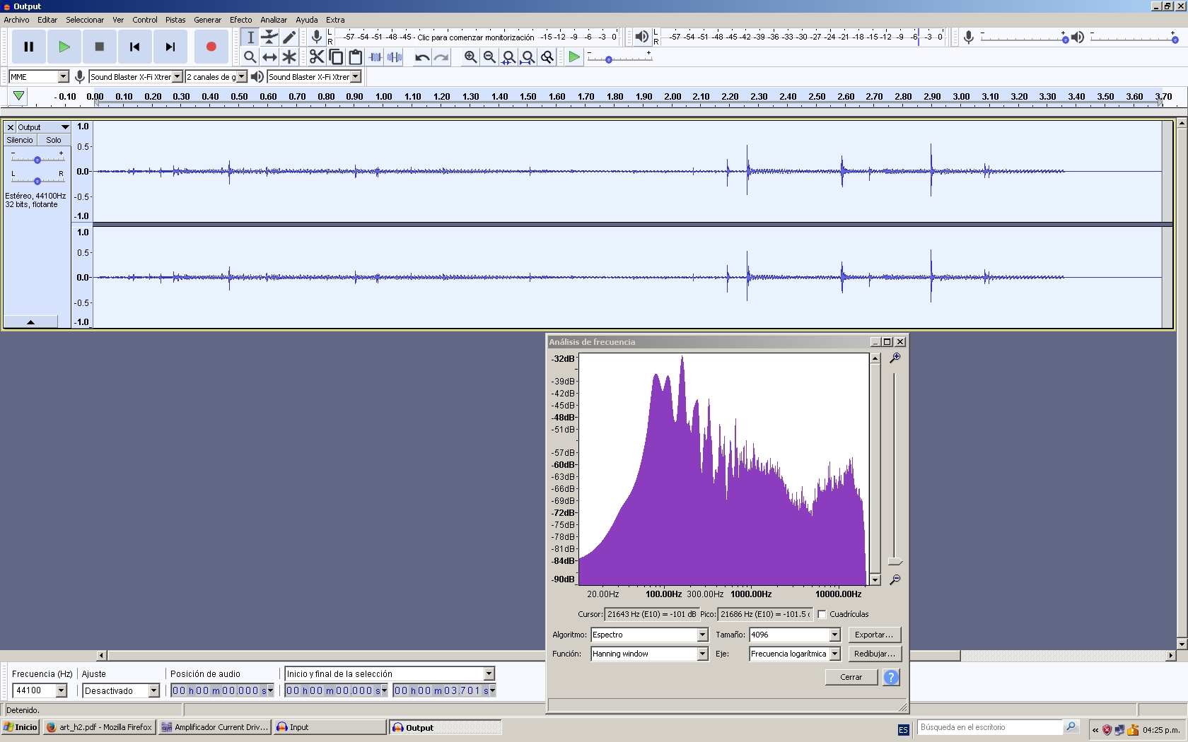
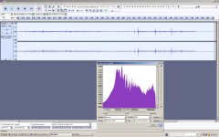
Although the circuit has a gain of 22.45 dB, I have decided to place a resistive divider (R8 and R9) in order to rescue an output signal with an amplitude very close to the input signal. Then, with the help of a simple program like Audacity, I record both signals (the one that is injected into the circuit and the one that is extracted from the output through the divider). I take the precaution of effecting the phase inversion of the output signal. Then, I compare both signals and try to listen and observe some subtle difference. I must admit that the signal that "makes virtually sing" the particular amplifier is monophonic and that is my limitation in the virtual evaluation.
The input signal can be heard by unzipping the .zip file called Input.zip. The file is in .wav format sampled at 44100 Hz, 32 bits floating.
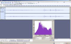
You can hear the output signal by unzipping the .zip file called Output.zip. The file is in .wav format sampled at 44100 Hz, 32 bits floating.
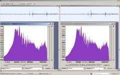
There was something that caught my attention in the form of the output signal: observe carefully where the signal approaches 0.5 V peak (it would seem to present some symmetry between the positive and negative part of the signal, unlike the signal that is injected into the circuit).


Best regards
Diego
With this circuit, I will run a virtual evaluation using simultaneously Multisim 14 and useful LabView tools. The idea is to inject a file fragment in the .wav format into the test circuit, so that its maximum amplitude tends to make the circuit work at a point close to that proposed by Mr. Nelson Pass. This point would be the one that causes a distortion with a profile defined between H2, H3 and H4 like the one that can be seen in the following figure. It corresponds to a THD of around 0.9% and is given for an input signal of 0.5 V peak.
Although the circuit has a gain of 22.45 dB, I have decided to place a resistive divider (R8 and R9) in order to rescue an output signal with an amplitude very close to the input signal. Then, with the help of a simple program like Audacity, I record both signals (the one that is injected into the circuit and the one that is extracted from the output through the divider). I take the precaution of effecting the phase inversion of the output signal. Then, I compare both signals and try to listen and observe some subtle difference. I must admit that the signal that "makes virtually sing" the particular amplifier is monophonic and that is my limitation in the virtual evaluation.
The input signal can be heard by unzipping the .zip file called Input.zip. The file is in .wav format sampled at 44100 Hz, 32 bits floating.
You can hear the output signal by unzipping the .zip file called Output.zip. The file is in .wav format sampled at 44100 Hz, 32 bits floating.
There was something that caught my attention in the form of the output signal: observe carefully where the signal approaches 0.5 V peak (it would seem to present some symmetry between the positive and negative part of the signal, unlike the signal that is injected into the circuit).
Best regards
Diego
Attachments
-
 H2 Circuit Generator.jpg190.8 KB · Views: 1,390
 -
 H2 Fourier Analysis.jpg356.3 KB · Views: 1,365
 -
 Input Espectral.jpg532.4 KB · Views: 1,350
 -
 Output Espectral.jpg541.9 KB · Views: 1,358
 -
 Espectral Comparison.jpg567.9 KB · Views: 1,351
 -
Input.zip469.8 KB · Views: 66
-
Output.zip466.8 KB · Views: 71
-
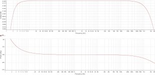 H2 Circuit Bode.jpg571.9 KB · Views: 1,375
Last edited:
You are looking at the wrong spot. At the point where the red fundamental
is positive, you will see that the blue is negative. Same for when the red is
peaking negative.
I know that it tends to be confusing.....
What I think is confusing to me is that "red goes up" over half the waveform. Do you really mean the positive peak of the red waveform?
The red fundamental goes up and down at a 1 KHz rate, and we see that the blue wave goes up and down as well at twice the frequency, but aligned with the red wave in a particular way -
the blue goes down when the red goes up and the blue also goes down when the red goes down.
Would it be better to say there is a blue negative peak near the time of the red positive peak and also a blue negative peak near the time of the red negative peak?
Because the blue trace is twice the frequency of the red trace, it has the same polarity peaks at both the positive and negative peaks of the red trace. (See points 1 and 2 in the attachment.) When you flip the picture, you flip both traces and the upper red peak aligns with a blue peak that has been inverted.
The search engine can't find SIT-1. Is there a thread where I can find out more about it?
Attachments
Last edited:
It is isn't it. Perhaps would be easier if we call the positive peak a 'peak' and the negative peak a 'valley'....The whole business of phase of H2 and the inverting nature of the H2 generator is still confusing. ...
A negative phase second harmonic has the valleys (negative) of the blue trace (the second harmonic with double the frequency) approximately line up with both the peaks and valleys of the red trace. A positive phase second harmonic has the peaks (positive) approximately line up with the peaks and valleys of the fundamental red trace.
Inverting amplifier means the peaks of the red trace (output) coincide with the valleys of the input (not shown).
The "Danyuk Resistor" calculated to be 63 Ohms for the J112 JFET I was using. The graphs below depict THD for different values of Vss with and without degeneration. Plot #5 on each graph is where H2 canceled. Very touchy to adjust the lab power supply to find the null. At lower values of Vss, the H2 phase is positive, at higher values, H2 phase is negative if I understand the article.
Nice work and very interesting...reading the curves I get:
20V: a little more than 1% THD, mostly 2. Harmonic
21.96V: 0.02% THD, no 2. Harmonic
25V: 0.3% THD, mostly 2. Harmonic
Could you repeat the test with Mr. Pass +/-0.3V range around the 21.96V, being the range 21.66...21.96...22.26V?
Does your memory tell you that having two 330 ohm resistors in place, as shown, is in some way better than having zero 330 ohm resistors, and also better than having one 330 ohm resistor? That would surprise me.
Mark, I dusted the cobwebs off my grey cells and also fired up the steamulator...
I don’t know about better: the 330 ohm resistor does affect a few things including dc offset but notably, doesn’t change H2 by comparison to no 300R. Nor is H2 increased by comparison to a 150R resistor in each emitter of the ltp...
The effect of imbalanced emitter degeneration in long tailed pairs seems always tied inextricably to what the stage is being used for and I Guess that what’s fascinating about them (well at lest to me)
And I think this is now OT but happy to continue the interesting discuioon on LTPs elsewhere.
I'm curious if those analog harmonic generators would sound different from the widely available digital counterpart today. I have tried many of them, but I ended up removing them from the signal chain.
HoRNet Harmonics, free waveshaper VST, AAX and Audio units plugin
Vertigo VSM-3 - Plugin Alliance
How to Add Harmonic Distortion for Analog Warmth | Waves
Too many to be listed here.
PS: If you can't go to BA2018 and/or just want to try them, insert one of those plugins (mostly free trial) in Audirvana (free trial), and playback Tidal highRez MQA (free trial). Vertigo VSM-3 is probably the best sounding one. Someone says it sounds the same as $7000 hardware mastering version.
Vertigo Sound VSM-2 Mix Satellite MK2 - Full Version - Vintage King Pro Audio Outfitter
Last edited: