Eureka , now it is as undersandable as a ZM circuit !
Hope you would not running nude !
U3 Drain is connected to GND and Supply Rail at the same time?
Yes, it does for having a reversal effect in H2 generation.
well, not to ZM

Juanitox meant that he will polish your circuit with sand paper.
Cheers all
Mondayitis? Not really, back to 6J1P driver for a final decision.
In a crudely state this EBay preamp is full of noise from 12Vac doubler.
Her plate voltage and current are governed only by a resistor, no hated here, just seen it as an unpolished opal.
Will combined with DN2540 as CCS and perhaps another EBay order for an 6J1P preamp to be modified as buffer but within Mr Pass philosophy “simple and elegant” .
Received my second 6J1 kit, then a quick and dirty modification happened for a buffering purpose (google search “6J1 site:www.diyaudio.com”
Preliminary measurements taken for conceiving a LateSit version 3, will be interesting due to direct negative H2 generation from tube, then Sit and Late mosfet have to be non reversal to have negative H2 output.
Please note, the LateSit is my long term project for personal education and entertainment.
The 6J1 preamp and buffer are behaving within normal limit of an Au $9 each, delivered, please find attached my measurements taken.
Cheers
.
Attachments
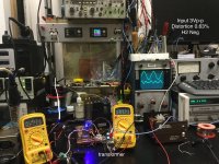
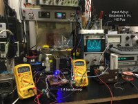
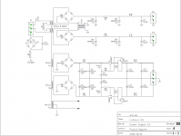
Reference Amplifier
So far I am successfully “LateSitted” the DefiSit(C) up to its transformer gain stage (without the pair K170 & J74).
The result is very impressive, due to high transconductance of the lateral BUZ905D and very low distortion of 1:4 transformer ( wire gain, hihi, I realised it when I built my Zeus amp).
Preliminary measurement recorded as a reference for later comparison with difference input gain and buffering driver circuit.
Clipping at 5Vp-p input, interesting at 4Vp-p input, the output H2 shifted from negative to positive phase.
Attachments
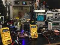
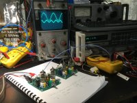
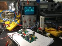
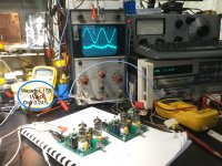
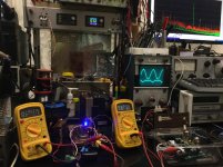
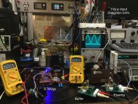
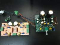
Preliminary test 6J1 buffer and preamp
The result is very poor, perhaps it does need a regulated and low noise power supply, the built in 12v tripler contributed a lot of noise to the circuit.
The result is very poor, perhaps it does need a regulated and low noise power supply, the built in 12v tripler contributed a lot of noise to the circuit.
Attachments
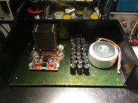
Chassis Day
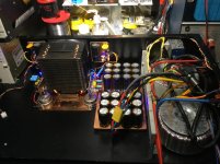
The wicked fan cooling is working extremely well, able to sink 150W for both channels with minimum fan speed.
Only problem is the height is 1cm taller than the U3 case.
Well, the copper plate has to go under the chassis!
The wicked fan cooling is working extremely well, able to sink 150W for both channels with minimum fan speed.
Only problem is the height is 1cm taller than the U3 case.
Well, the copper plate has to go under the chassis!
Attachments
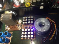
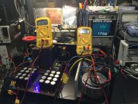
Using CRC filtering with el cheapo caps, just to find out how long would they last to the ripple current...
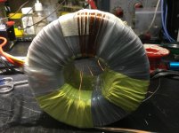
My toroid 2 x 24Vac @ 150VA, provides around 32Vdc under load, needs to be wind back to 28~30 for CRC voltage safety margin.
Too lazy to remove few turns from secondary coils, I thought about using LCRC that I learnt from “Eduard & nagini262” with bifilar Ls in differential mode
Type of Choke for CLC?.
Empirically I found the secondary 2 x 12Vac 100VA toroid is my best candidate, it does reduced the output to 28Vdc under load with 0.01Vpp ripple.
Attachments
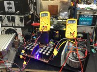
...with el cheapo caps, just to find out how long would they last to the ripple current...
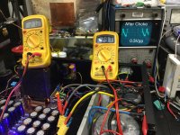
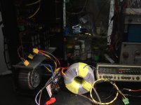
I had a look at the ripple V out of both circuits:
CRC (60mF - 0.5R - 60mF)
LCRC (dual 12Vac secondary coils - 60mF - 0.5R - 60mF)
Vripple are all 0.01Vpp on my CRO.
But at the input to the first capacitor, the difference is huge.
17Vpp before choke and 0.3Vpp after choke
These voltages reveal that ripple current is reduced to a safe margin for low cost capacitor or expensive “audio grade” one.
.
Attachments
...
These voltages reveal that ripple current is reduced to a safe margin for low cost capacitor or expensive “audio grade” one.
.
Another benefit of LC Filter is ripple energy is not wasted as heat, it is transformed to magnetic flux and regulated the the energy’s transfer without the need of excessive high VA for power transformer. It is surpassing the SMPS in this field to provide fast and punching characters.
Thermal and power supply tests been conducted in 48 hours continuously, a dollar 10mF/35V capacitor is helpfully stretched my wallet far beyond expectation.
LateSit amp with two 6J1 cards, preamp and buffer modified from cheap kits.
YouTube
Cheers
Attachments
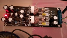
DN2540 SRPP DRIVER
I use an TL431 adjustable voltage regulator for biasing the PA stage, the bias circuit is separately from the driver, that eliminates bias retuning when swapping different driver.
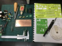
Built:
1) Wire Gain, 1:4 transformer with BF862 buffer input stage.
2) DN2540 SRPP.
Next week:
3) Yours proletariately el cheapo Korg B1 with a dollar 6J1 or 4 dollars 6C51H-B with BF862 buffers
Cheers
I use an TL431 adjustable voltage regulator for biasing the PA stage, the bias circuit is separately from the driver, that eliminates bias retuning when swapping different driver.
Built:
1) Wire Gain, 1:4 transformer with BF862 buffer input stage.
2) DN2540 SRPP.
Next week:
3) Yours proletariately el cheapo Korg B1 with a dollar 6J1 or 4 dollars 6C51H-B with BF862 buffers
Cheers
Attachments
Next week:
3) Yours proletariately el cheapo Korg B1 with a dollar 6J1 or 4 dollars 6C51H-B with BF862 buffers
Cheers
Hi
I like what you did. I also tried using thoae cheapo tube buffers, but was disapointed due to their poor perfirmance. In fact, the whole thing needs so many modfications to make it "right" so that it is almost easier to build it from scratch rather than mod the board. First, the voltage tripler is noisy, so it must be abandoned and the while PSU rebuilt properly. Second, the two 6j1 tubes on board have their heaters wired in series, then to 12 V AC unregulated. So you see what this means. In my case it was noisy and humming buffer. I have since put It in a box called "forgetaboutit". Well, maybe one day I will re-build it properly...
Also, one question: What is the phase of the second harmonic that is generated by the tube? Positive or negative?
Regards,
Vix
Attachments
Hi
... it is almost easier to build it from scratch rather than mod the board.
Also, one question: What is the phase of the second harmonic that is generated by the tube? Positive or negative?
Regards,
Vix
Salut
In my case, modify the 6J1 board is quicker to start from scratch and more economic. I have very little experience with hollow state, so take it as an opportunity to understand about triode.
The second harmonic generated at 1000 Hz input by 6J1 is negative -H2.
Post #63
LateSit
Cheers
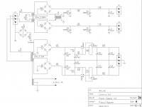
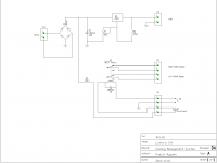
Cooling Management System
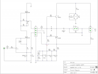
For an active cooling system, if the forced air movement is interrupted by faulty fan or blocked airways, temperature will raise rapidly above the SOA.
To prevent such an incident could occurred, I managed to use an 50 C thermostat with normally open switch.
Over 50 C, the switch is closed, establishing a relay to deenergise all bias supplies (Left and Right) and light up an ‘overheat’ LED. Then bias voltage will drop to zero, SIT will fully conducted and Lateral MOSFET will stop conducting, like 2 switches in series with one ON and one OFF. The amp will cease functioning.
The fan speed is regulated by an 7805 with 2 resistors for voltage adjustment.
Errors in the dwg, please change to:
- LED To pin 1 and 2
- Thermostat To pin 3 and 4
.
Attachments
Last edited:
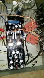
Power Supply with single transformer
For vacuum tubes driver, I intended to use a separate transformer for filaments and high voltage.
Unfortunate or fortunate, I don’t have any room left for an extra trany, so need to be brave to redo the PS with three extra coils for my vacuum tubes.
.
For vacuum tubes driver, I intended to use a separate transformer for filaments and high voltage.
Unfortunate or fortunate, I don’t have any room left for an extra trany, so need to be brave to redo the PS with three extra coils for my vacuum tubes.
.
Attachments
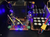
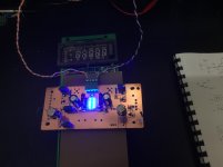
Bluescein
Hi Alex
Got an VFD with all peripherals for microwave oven, could not find any string that can play as a grid role.
Thanks for remind me about “luminophore”, I had a thought about using fluorescein in water cooling with transparent casing for my next project.
In the mean time I am happy with a bluescein effect from a string of blue leds.
Cheers
Drill some holes and sprinkle with luminophore.
Seriously: you may try to use Vacuum Fluorescent Display, seven segment VFD for instance instead of B1. Could not find reference design though.
Hi Alex
Got an VFD with all peripherals for microwave oven, could not find any string that can play as a grid role.
Thanks for remind me about “luminophore”, I had a thought about using fluorescein in water cooling with transparent casing for my next project.
In the mean time I am happy with a bluescein effect from a string of blue leds.
Cheers
Attachments
Hi Alex
Got an VFD with all peripherals for microwave oven, could not find any string that can play as a grid
My ignorance about the structure of VFD.
Just find out where the grid is. Very interesting.
An externally hosted image should be here but it was not working when we last tested it.
https://www.instructables.com/id/VFD-Amplifier-a-Tube-Amp-From-VCR-Screens/
- Status
- This old topic is closed. If you want to reopen this topic, contact a moderator using the "Report Post" button.
- Home
- Amplifiers
- Pass Labs
- LateSit