One quirk of the hugely popular ACA that seems to regularly get a mention relates to the strange noise it can make at power on and the loud thump that occurs at switch off. This kind of behaviour is actually 'normal' for pretty much any AC coupled amplifier. AC coupling here relates in the main to the large speaker coupling capacitor and the fact this has to both charge and discharge via the load (your speaker) when power is applied and removed.
It is also possible (you would have to confirm or otherwise) that the SMPS may 'ramp' up the voltage due to momentary current limiting becoming active at power on.
At this point I have to say I have never built an ACA and so ALL that follows is 100% theoretical, however those interested enough to delve a little deeper may find some ideas in amongst all of this on how to make it virtually silent.
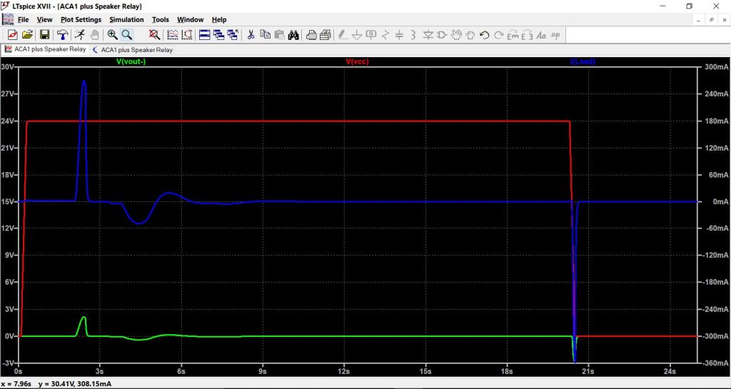
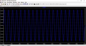
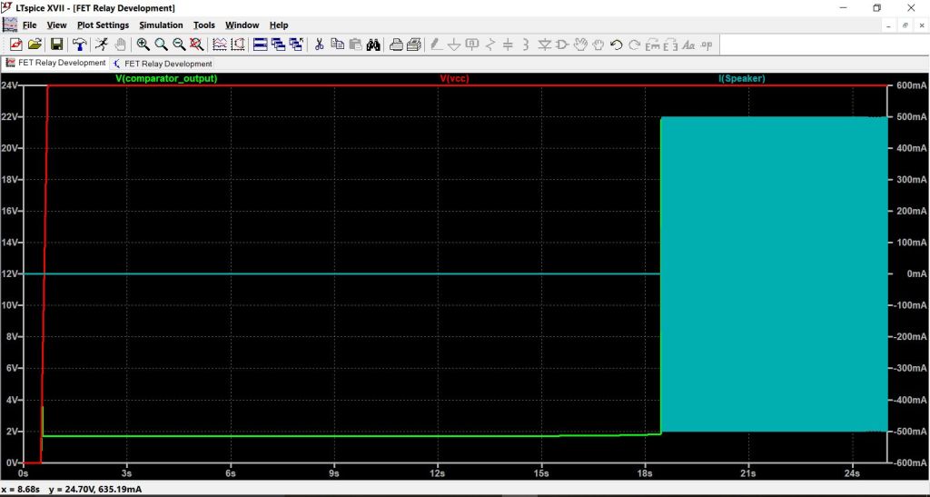
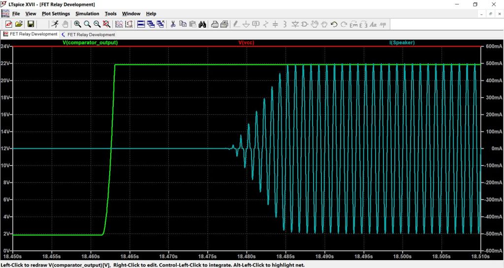
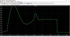
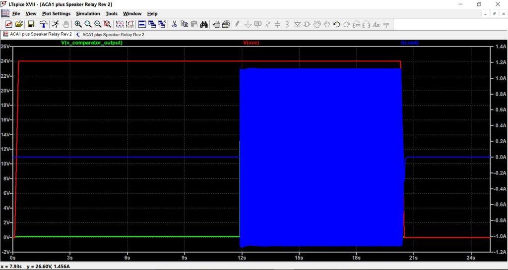
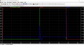
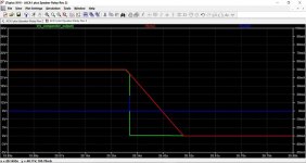
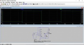
A graphical representation shows the problem. Here we have a simulation of an ACA showing the sequence of events as power is applied. The supply voltage and amplifier output voltage (the black speaker terminal) are shown with reference to the left hand voltage scale. The load current (your speaker) is referenced to the scale at the right. We can immediately see the large switch on thump and an even larger switch off related event. The ACA has no signal applied during this test.
Is it possible to eliminate this and give a silent start up and shutdown ?
Using a speaker relay would be considered one possible route, however relays are a little power hungry and can suffer from contact degradation over time. This isn't some imaginery issue that happens to other people... its happened to me... and as witnessed by many threads on these forums it also happens to many others as well.
One real alternative is a solid state relay contstructed from two back to back power MOSFET's. These are becoming more and more popular because they suffer no degradation in use, and have a current switching capacity limited only by the FET rating. Voltage rating of this type of relay is again determined by the FET. The series resistance (what would be contact resistance in a traditional relay) is twice the value of the Rds of the chosen FET.
Downsides of the FET relay.
In practice when used for speaker switching duty, one real problem is that of providing the necessary gate drive voltage. The reason for this is that the drive voltage would normally have to be 'floating' and not referenced to ground or the supply rail.
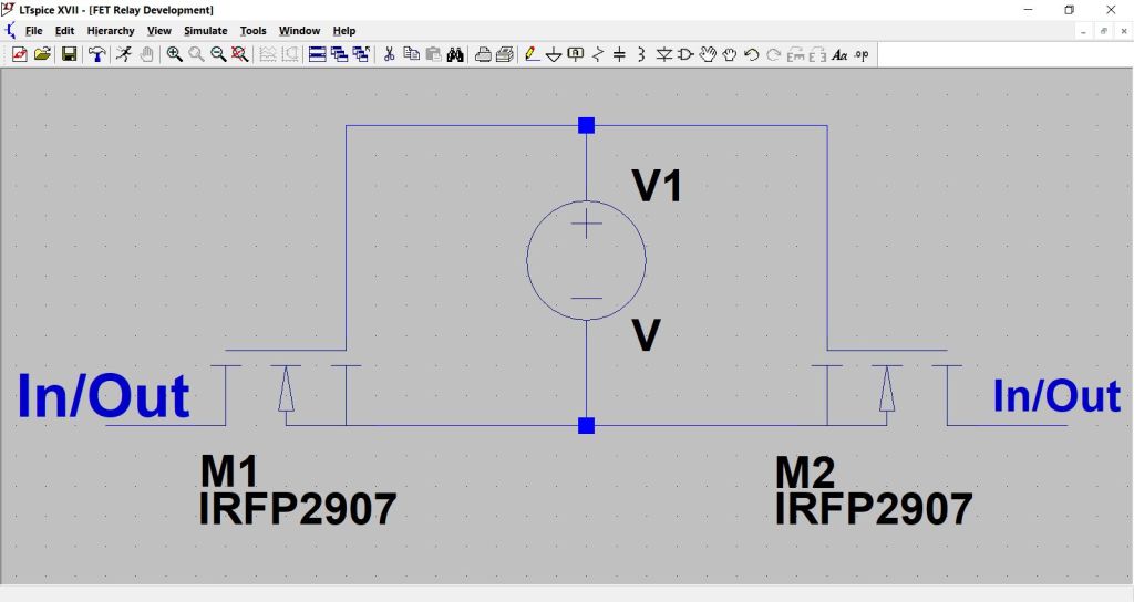
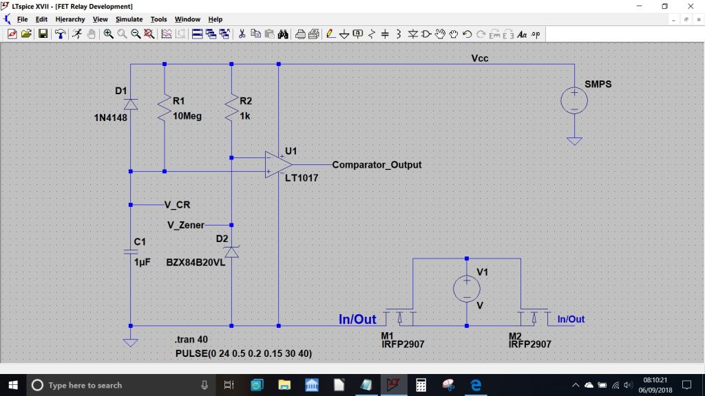
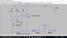
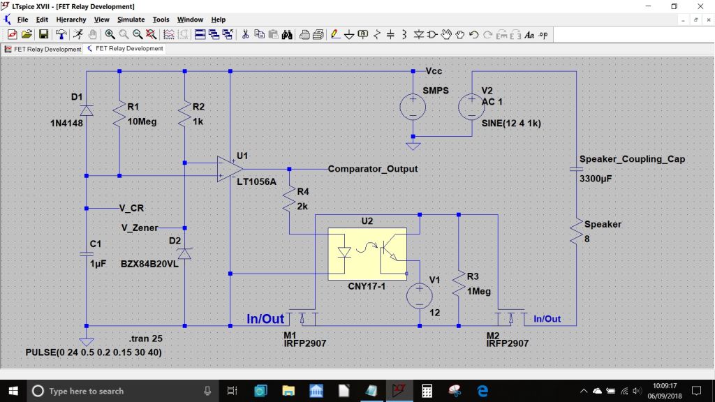
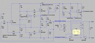
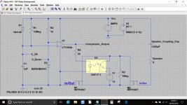
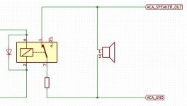
The following explores the FET relay in more detail and the diagram below is a practical relay constructed from two N Channel power FET's. The key to the relays success relies on the drive voltage V1 being floating. If that requirement is met then the relay behaves as expected and is truly bi-directional, just like a mechanical one. In this form the relay is suitable for speaker switching duty in both AC coupled amps and also DC coupled running off a dual supply.
The floating drive voltage is traditionally derived from a 'Photovoltaic Coupler' which can be thought of as being like a tiny solar cell that is illuminated by an LED. When the LED lights, the cell generates voltage (typically 7 volts), and this voltage is applied as a floating source between gate and source to turn the FET's on or off. The whole thing is often drawn in a similar way to a standard opto coupler and packaged in the same manner. The on/off isolation of this type of relay is excellent at DC and low frequencies, and becoming worse at high frequency due to the junction capacitance of the FET's. In practice this is a non problem for our application because the load being switched is (relatively speaking) of very low impedance.
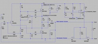
Turning now to the ACA, we have the option of placing such a relay in either the speaker positive or speaker negative feed. It is simply a series switch and so in that sense it doesn't really matter where in the circuit it is placed.
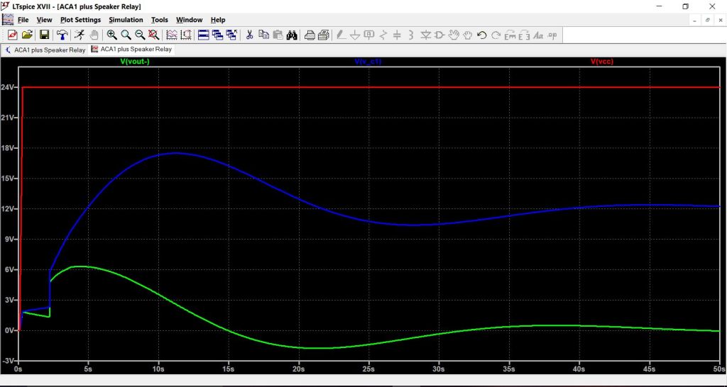
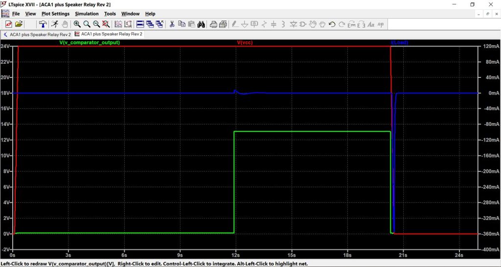
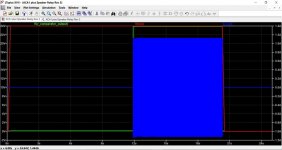
Before considering what may be possible we first have to look in detail at the problem we are trying to solve. Although it may seem obvious when mentioned, one real factor to be considered is that when the speaker is not connected, the time constant of the speaker coupling cap and R14 (whcih is the caps only means of charging) is large.
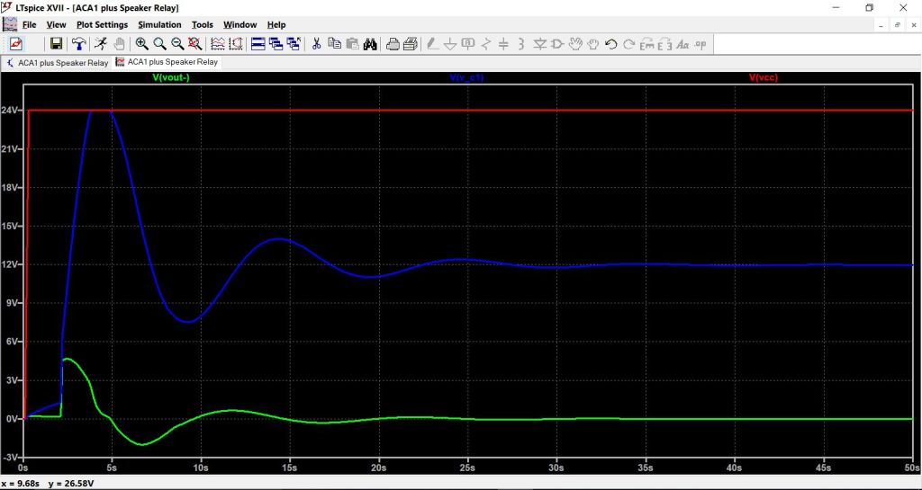
We can see that below. Here the speaker is not connected.
There is no easy way around this long time constant. Technically complex solutions would be to employ a low value shunt resistor to give a super quick charge time, the resistor then being switched out of circuit. In the ACA about the best we can do is to reduce the value of R14 and that is what is done here. Reducing by a factor of ten gives us something more realistic to work with, and now we could reasonably say that a delay of 20 to 25 seconds should give a much reduced switch on thump. The longer the delay, the quieter its going to be. Given the low power output of the ACA a 1 watt 100 ohm is more than adequate.
So having come up with a suitable solid state relay, and now having some idea of the delay needed the next step in the design process would be to construct some form of drive circuit for the FET relay. The ACA does us some favours here because of the fact it runs on a tightly regulated supply with very defined start up and shut down characteristics.
(I know the start up and shut down behaviour of the SMPS will be tightly defined, the trouble is that I don't know exactly what the numbers might be with regard to supply rise and fall times and so I'm going to have to make some assumptions)
A simple comparator seems a likely possibility to begin the design and only one is needed because both ACA channels would share the drive circuitry.
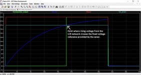
So firstly we have to set up our supply rail in the simulation and for this I am choosing a rise time of 200ms and fall time of 150ms. Next we add the comparator and set an R/C time delay on the inverting input. The non inverting input is fixed at 20 volts by the zener diode.
The operation is as follows. When the supply voltage appears, the RC network delays the rise in voltage at the comparator input. It is the classic exponential charge curve. When this rising voltage crosses the fixed level provided by the zener we see that the comparator output flips from low to high. This voltage can then be used to operate our relay. The function of the diode is simply to dump the charge in the timing cap back into the supply rail when power is removed. This allows the circuit to be instantly ready to work again if needed.

Putting it all together.
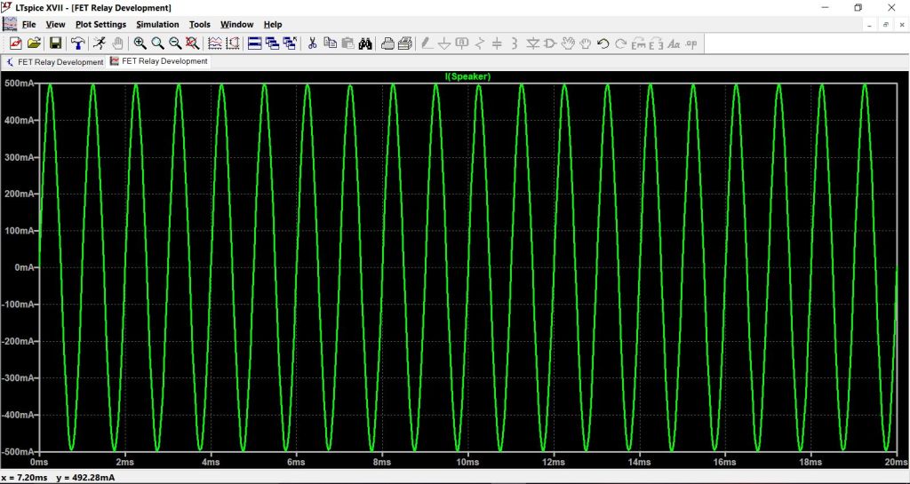
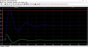
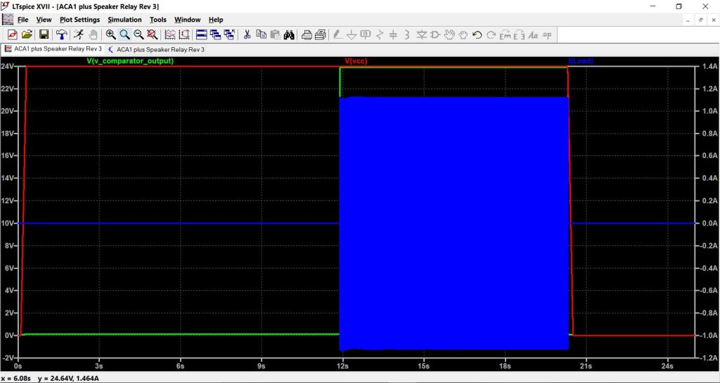
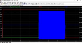
The following shows the relay in the off state (that floating voltage source between G and S is zero). The upp er right voltage source represents the ACA and is a 4 volt peak sinewave (1 watt/8ohm) riding on a DC voltage of 12 volts. The plot shows the load current (leakage) which is pretty small.

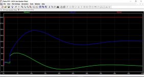
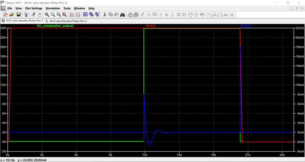
Now we change the floating voltage source to 12 volts which will fully turn on the FET's. Again we look at the load current and can see that the FET's behave as if they were essentially a wire link or short. A near perfect relay.
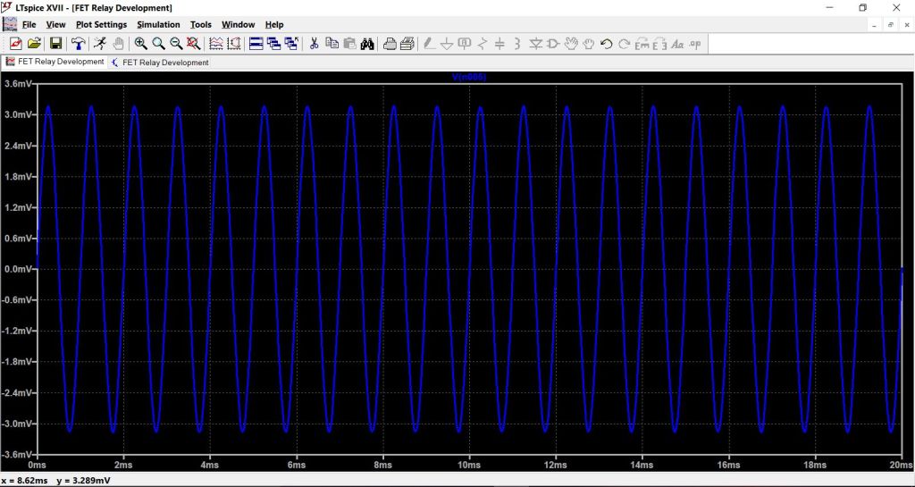
This shows the voltage at the 'earthy' end of the load, in other words the voltage lost across the relay. The lower the Rds value, the lower the losses.
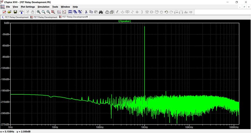
(Audiophile hint") using FET's with a higher Rds has the effect of reducing the damping factor. Heretical audiophile hint Using dissimilar FET's might be felt to introduce a very low level 'pleasant' even order distortion profile to the resultant current passing through the relay)
using FET's with a higher Rds has the effect of reducing the damping factor. Heretical audiophile hint Using dissimilar FET's might be felt to introduce a very low level 'pleasant' even order distortion profile to the resultant current passing through the relay)
It is also possible (you would have to confirm or otherwise) that the SMPS may 'ramp' up the voltage due to momentary current limiting becoming active at power on.
At this point I have to say I have never built an ACA and so ALL that follows is 100% theoretical, however those interested enough to delve a little deeper may find some ideas in amongst all of this on how to make it virtually silent.
A graphical representation shows the problem. Here we have a simulation of an ACA showing the sequence of events as power is applied. The supply voltage and amplifier output voltage (the black speaker terminal) are shown with reference to the left hand voltage scale. The load current (your speaker) is referenced to the scale at the right. We can immediately see the large switch on thump and an even larger switch off related event. The ACA has no signal applied during this test.
Is it possible to eliminate this and give a silent start up and shutdown ?
Using a speaker relay would be considered one possible route, however relays are a little power hungry and can suffer from contact degradation over time. This isn't some imaginery issue that happens to other people... its happened to me... and as witnessed by many threads on these forums it also happens to many others as well.
One real alternative is a solid state relay contstructed from two back to back power MOSFET's. These are becoming more and more popular because they suffer no degradation in use, and have a current switching capacity limited only by the FET rating. Voltage rating of this type of relay is again determined by the FET. The series resistance (what would be contact resistance in a traditional relay) is twice the value of the Rds of the chosen FET.
Downsides of the FET relay.
In practice when used for speaker switching duty, one real problem is that of providing the necessary gate drive voltage. The reason for this is that the drive voltage would normally have to be 'floating' and not referenced to ground or the supply rail.
The following explores the FET relay in more detail and the diagram below is a practical relay constructed from two N Channel power FET's. The key to the relays success relies on the drive voltage V1 being floating. If that requirement is met then the relay behaves as expected and is truly bi-directional, just like a mechanical one. In this form the relay is suitable for speaker switching duty in both AC coupled amps and also DC coupled running off a dual supply.
The floating drive voltage is traditionally derived from a 'Photovoltaic Coupler' which can be thought of as being like a tiny solar cell that is illuminated by an LED. When the LED lights, the cell generates voltage (typically 7 volts), and this voltage is applied as a floating source between gate and source to turn the FET's on or off. The whole thing is often drawn in a similar way to a standard opto coupler and packaged in the same manner. The on/off isolation of this type of relay is excellent at DC and low frequencies, and becoming worse at high frequency due to the junction capacitance of the FET's. In practice this is a non problem for our application because the load being switched is (relatively speaking) of very low impedance.
Turning now to the ACA, we have the option of placing such a relay in either the speaker positive or speaker negative feed. It is simply a series switch and so in that sense it doesn't really matter where in the circuit it is placed.
Before considering what may be possible we first have to look in detail at the problem we are trying to solve. Although it may seem obvious when mentioned, one real factor to be considered is that when the speaker is not connected, the time constant of the speaker coupling cap and R14 (whcih is the caps only means of charging) is large.
We can see that below. Here the speaker is not connected.
There is no easy way around this long time constant. Technically complex solutions would be to employ a low value shunt resistor to give a super quick charge time, the resistor then being switched out of circuit. In the ACA about the best we can do is to reduce the value of R14 and that is what is done here. Reducing by a factor of ten gives us something more realistic to work with, and now we could reasonably say that a delay of 20 to 25 seconds should give a much reduced switch on thump. The longer the delay, the quieter its going to be. Given the low power output of the ACA a 1 watt 100 ohm is more than adequate.
So having come up with a suitable solid state relay, and now having some idea of the delay needed the next step in the design process would be to construct some form of drive circuit for the FET relay. The ACA does us some favours here because of the fact it runs on a tightly regulated supply with very defined start up and shut down characteristics.
(I know the start up and shut down behaviour of the SMPS will be tightly defined, the trouble is that I don't know exactly what the numbers might be with regard to supply rise and fall times and so I'm going to have to make some assumptions)
A simple comparator seems a likely possibility to begin the design and only one is needed because both ACA channels would share the drive circuitry.
So firstly we have to set up our supply rail in the simulation and for this I am choosing a rise time of 200ms and fall time of 150ms. Next we add the comparator and set an R/C time delay on the inverting input. The non inverting input is fixed at 20 volts by the zener diode.
The operation is as follows. When the supply voltage appears, the RC network delays the rise in voltage at the comparator input. It is the classic exponential charge curve. When this rising voltage crosses the fixed level provided by the zener we see that the comparator output flips from low to high. This voltage can then be used to operate our relay. The function of the diode is simply to dump the charge in the timing cap back into the supply rail when power is removed. This allows the circuit to be instantly ready to work again if needed.
Putting it all together.
The following shows the relay in the off state (that floating voltage source between G and S is zero). The upp er right voltage source represents the ACA and is a 4 volt peak sinewave (1 watt/8ohm) riding on a DC voltage of 12 volts. The plot shows the load current (leakage) which is pretty small.
Now we change the floating voltage source to 12 volts which will fully turn on the FET's. Again we look at the load current and can see that the FET's behave as if they were essentially a wire link or short. A near perfect relay.
This shows the voltage at the 'earthy' end of the load, in other words the voltage lost across the relay. The lower the Rds value, the lower the losses.
(Audiophile hint
using FET's with a higher Rds has the effect of reducing the damping factor. Heretical audiophile hint Using dissimilar FET's might be felt to introduce a very low level 'pleasant' even order distortion profile to the resultant current passing through the relay)Attachments
-
 ACA 1R.jpg70.7 KB · Views: 1,759
 -
 ACA 9R.jpg89.6 KB · Views: 1,663
 -
 ACA 8R.jpg112 KB · Views: 1,641
 -
 ACA 7R.jpg110 KB · Views: 1,667
 -
 ACA 6R.jpg83.3 KB · Views: 1,673
 -
 ACA 5R.jpg91.7 KB · Views: 1,671
 -
 ACA 4R.jpg67.4 KB · Views: 1,663
 -
 ACA 3R.jpg68.7 KB · Views: 1,700
 -
 ACA 2R.jpg50.2 KB · Views: 1,680
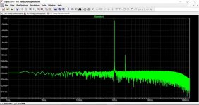
This is a distortion plot of the current passing through the load. The first example is with similar FET's, the second with dissimilar.

Getting it all to work.
This is where it gets more difficult. The photovoltaic coupler is the sure-fire way to get a truly floating drive voltage, the downside being the cost... although of course in the scheme of things its all relative. They are not that expensive. We also have the problem of how to simulate this. I came up with the idea of using a traditional optocoupler and a fixed 12 volt source. Lets see how that works out.
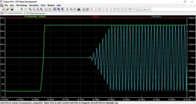
This shows the idea in action. The audio is muted until the comparator changes state, at which point the relay closes and audio is passed. The third image shows a close up of the moment the relay turns on. A practical relay using a photovoltaic coupler would need no other components apart from the coupler and FET's. The 1meg in the simulation is to stop the tiny leakage of the opto coupler model from interfering with the off state of the relay.
Testing the idea with the actual ACA simulation.
This is where issues come to light, however, these may be more down to the simulation than a real problem. Specifically, the main problem is seeing a switch off thump (current in the speaker) when the relay should be off. I know from having used these relays that they behave as expected and so I'm left wondering if the issue here really is simulation related.
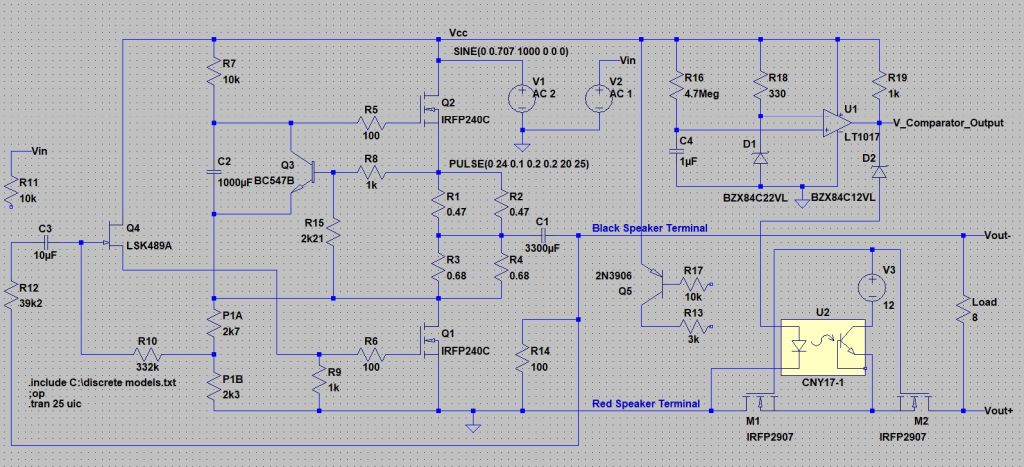
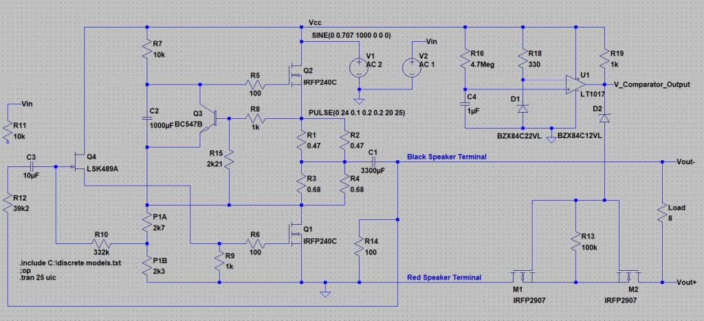
At this point we take a step back and redraw the circuit with a view to clarifying and simplifying. A different model for the opto seems to obviate the need for the 1meg resistor. In a real build it wouldn't matter anyway because the photovoltaic coupler is all that is needed. The comparator (LT1017) has an active class B output stage, however the current source ability is limited. This means we still need the traditional 'pull up' resistor to supply the LED in the coupler. A zener has also been included in the feed to the LED and this is purely to make absolutely sure the relay can not be forced into conduction due to any small glitches/transisions etc that may momentarily occur on the comparator output.
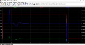
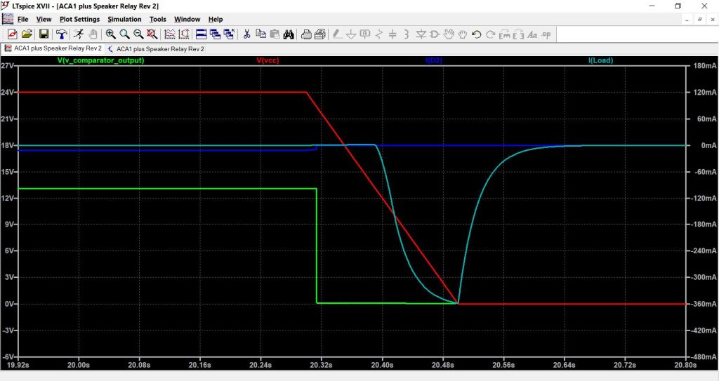
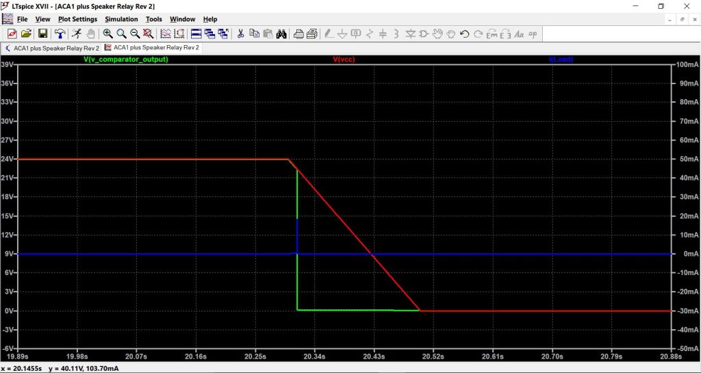
This shows our basic working circuit, and following on from that the voltage and currents at critical points in the design. You can see the supply voltage at the point of switch off together with the comparator output voltage and current in the Zener/LED feed. Note the speaker current. The small current pulse at around 12 seconds is solely due to the time delay chosen before the relay activates and 12 seconds is not long enough for the both the amplifier and its 3300uF speaker coupling cap to charge via the 100 ohm resistor (R14). How long a user would want to wait before the speaker was activated is down to personal choice.
Remember it is not just the 3300uF cap that is the problem here. The amplifier itself has a very long settling time, realistically around 18 seconds from power being applied as can be seen here.

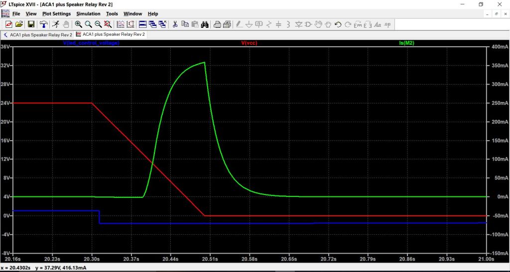
Now to the 'big' problem that may well just be a problem with the simulation. This shows the moment of switch off. Note the way the 24 volt rail collapses (one of my assumptions outlined at the start... I hope I have picked a realistic rise and fall time for the 24 volt rail), and in particular note how quickly and cleanly the comparator flips state removing drive current from the photovoltaic coupler. Once the drive current is removed, the relay is off and this is the puzzle/problem... the simulation goes on to show a current spike in the speaker that occurs after the relay is off. I have no answer to that besides saying that it shouldn't be doing it.
The big question. Is this current spike real or not ? If the relay were mechanical and driven by the comparator output voltage then the answer is a definite no, the relay must be off at that point in time and so no current can flow.
A real and practical solid state relay behaves like a mechanical one. So where does this spike come from ?
To elaborate on this further I took a plot of the current flow in the FET source lead and overlaid this with the relay on/off control voltage. The voltage on the LED assumes a slightly negative value... puzzlement over that... and so at this point I'm going to say that the behaviour of this in simulation is possible erroneous and that the a real photovoltaic coupler would work as expected.
So job done then, at least as far as a theoretical exercise is concerned. Well not quite... the photovoltaic coupler is a main cost item and so I wondered if it could be eliminated. The fact the ACA is single rail, and the fact the relay is in the negative speaker return suggests it might be possible. So lets see.
Getting it all to work.
This is where it gets more difficult. The photovoltaic coupler is the sure-fire way to get a truly floating drive voltage, the downside being the cost... although of course in the scheme of things its all relative. They are not that expensive. We also have the problem of how to simulate this. I came up with the idea of using a traditional optocoupler and a fixed 12 volt source. Lets see how that works out.
This shows the idea in action. The audio is muted until the comparator changes state, at which point the relay closes and audio is passed. The third image shows a close up of the moment the relay turns on. A practical relay using a photovoltaic coupler would need no other components apart from the coupler and FET's. The 1meg in the simulation is to stop the tiny leakage of the opto coupler model from interfering with the off state of the relay.
Testing the idea with the actual ACA simulation.
This is where issues come to light, however, these may be more down to the simulation than a real problem. Specifically, the main problem is seeing a switch off thump (current in the speaker) when the relay should be off. I know from having used these relays that they behave as expected and so I'm left wondering if the issue here really is simulation related.
At this point we take a step back and redraw the circuit with a view to clarifying and simplifying. A different model for the opto seems to obviate the need for the 1meg resistor. In a real build it wouldn't matter anyway because the photovoltaic coupler is all that is needed. The comparator (LT1017) has an active class B output stage, however the current source ability is limited. This means we still need the traditional 'pull up' resistor to supply the LED in the coupler. A zener has also been included in the feed to the LED and this is purely to make absolutely sure the relay can not be forced into conduction due to any small glitches/transisions etc that may momentarily occur on the comparator output.
This shows our basic working circuit, and following on from that the voltage and currents at critical points in the design. You can see the supply voltage at the point of switch off together with the comparator output voltage and current in the Zener/LED feed. Note the speaker current. The small current pulse at around 12 seconds is solely due to the time delay chosen before the relay activates and 12 seconds is not long enough for the both the amplifier and its 3300uF speaker coupling cap to charge via the 100 ohm resistor (R14). How long a user would want to wait before the speaker was activated is down to personal choice.
Remember it is not just the 3300uF cap that is the problem here. The amplifier itself has a very long settling time, realistically around 18 seconds from power being applied as can be seen here.
Now to the 'big' problem that may well just be a problem with the simulation. This shows the moment of switch off. Note the way the 24 volt rail collapses (one of my assumptions outlined at the start... I hope I have picked a realistic rise and fall time for the 24 volt rail), and in particular note how quickly and cleanly the comparator flips state removing drive current from the photovoltaic coupler. Once the drive current is removed, the relay is off and this is the puzzle/problem... the simulation goes on to show a current spike in the speaker that occurs after the relay is off. I have no answer to that besides saying that it shouldn't be doing it.
The big question. Is this current spike real or not ? If the relay were mechanical and driven by the comparator output voltage then the answer is a definite no, the relay must be off at that point in time and so no current can flow.
A real and practical solid state relay behaves like a mechanical one. So where does this spike come from ?
To elaborate on this further I took a plot of the current flow in the FET source lead and overlaid this with the relay on/off control voltage. The voltage on the LED assumes a slightly negative value... puzzlement over that... and so at this point I'm going to say that the behaviour of this in simulation is possible erroneous and that the a real photovoltaic coupler would work as expected.
So job done then, at least as far as a theoretical exercise is concerned. Well not quite... the photovoltaic coupler is a main cost item and so I wondered if it could be eliminated. The fact the ACA is single rail, and the fact the relay is in the negative speaker return suggests it might be possible. So lets see.
Attachments
-
 ACA 18R.jpg77.5 KB · Views: 1,580
 -
 ACA 17R.jpg74 KB · Views: 1,617
 -
 ACA 16R.jpg73.5 KB · Views: 1,629
 -
 ACA 15R.jpg113.1 KB · Views: 1,584
 -
 ACA 14R.jpg106 KB · Views: 1,621
 -
 ACA 13R.jpg68 KB · Views: 1,649
 -
 ACA 12R.jpg103.3 KB · Views: 1,606
 -
 ACA 11R.jpg100.2 KB · Views: 1,629
 -
 ACA 10R.jpg94.4 KB · Views: 1,627
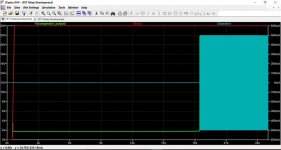
I have to say I was amazed at the result. Can we trust this ? The switch off pulse is minimal and the circuit very simple.
So finally here are the two versions to compare, each tested at no signal and full output. That large switch off pulse looks bad and yet everything says it shouldn't even be there with the Photovoltaic version, this method of using a floating voltage source (the photo voltaic coupler) being the 'gold standard'.
And the second version. Is it to good to be true ? This is the version that I would expect to be fussy on implementation... however the simulation says otherwise.
So that just about wraps up the theoretical side of this, the next step for any of those interested would be to actually build one and see. The design is easy to implement to try and test and can be literally 'tagged onto' the speaker output terminal with only a 24 volt feed needed.
Attachments
These are the .asc files for anyone wishing to see how the simulation behaves. These files were created using default models included in LT XVII
Attachments
Hi Mooly. I'm still deep in the learning stage so forgive me if this is a dumb question.
I was wondering if the delay in the mosfets shutting off could be due to the capacitance charge of the mosfets themselves? Could that be why it improved when you added the resistor between gate and source? Would a resistor to ground somewhere help at all?
I was wondering if the delay in the mosfets shutting off could be due to the capacitance charge of the mosfets themselves? Could that be why it improved when you added the resistor between gate and source? Would a resistor to ground somewhere help at all?
Its a good question and your reasoning could be correct
I tried quite a few things with the simulated photovoltaic coupler but I will re-run those simulations later and have a play. The real photovoltaic coupler (which I can't fully simulate) actually has an active turn off circuit within it.
The simple version with no coupler seemed to work better than expected and that included a 100k from gate to source to both eliminate any issue with stray pickup from what is a high impedance node (as its connected via a Zener) and it also aids removing charge.
It is an interesting effect though.
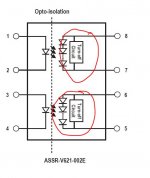
This is how the real coupler looks in block diagram form.
I tried quite a few things with the simulated photovoltaic coupler but I will re-run those simulations later and have a play. The real photovoltaic coupler (which I can't fully simulate) actually has an active turn off circuit within it.
The simple version with no coupler seemed to work better than expected and that included a 100k from gate to source to both eliminate any issue with stray pickup from what is a high impedance node (as its connected via a Zener) and it also aids removing charge.
It is an interesting effect though.
This is how the real coupler looks in block diagram form.
Attachments
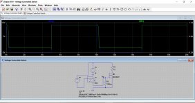
I rigged this up to try and see how the FET's behave when switched off. The switch supplying the gate has a 'nearly' infinite off resistance at 1000 Meg ohm. The 10 meg from gate to source discharges the gate capacitance.
Making the resistor 100k sharpens things up no end.
Making the resistor 100k sharpens things up no end.
Attachments
Just a quick thought while skimming through your thorough work: What about putting that solid state relay in parallel with the speaker and shunt that thump to ground? I for one would not like to wait half a minute for my amps to come on... (well, I'm already annoyed by two seconds turn-on delay )
)Well... a shorting relay is certainly another possibility.
I'm not sure how it would work in practice with a solid state relay because the circuit needs voltage to operate the relay, and voltage means the speaker cap is already charging. That would be a whole new design exercise I think.
A mechanical shorting relay would of course be closed at the crucial time.
It's an interesting idea though.
Hi Mooly. I'm still deep in the learning stage so forgive me if this is a dumb question.
I was wondering if the delay in the mosfets shutting off could be due to the capacitance charge of the mosfets themselves? Could that be why it improved when you added the resistor between gate and source? Would a resistor to ground somewhere help at all?
I've just run the simulations and looked into this and I think your reasoning is sound
in that retained charge on the gate is responsible for a big part of the switch off glitch. The opto used in the simulation seems critical to deciding on the value of resistor that could be used to shunt the gate and source of both FET's. A 100k stops the relay turning on whereas 1meg seems to work reasonably well.If anyone were to use the real deal (the photovoltaic coupler) then I think the problem would vanish due to the active turn off circuitry within the package.
I'll tidy the simulations up tomorrow hopefully and add them to the thread so that anyone can have a play around.
This is really interesting theoretical information.
I for one am very interested in the conceptual side of this (mostly because the on and off noises do not bother me at all). But this is way, waaaay, above my knowledge level to comprehend.
As an owner of an previews version of ACA, would there be any adjustments if the circuit where fed by 19V and biased to 10v?
Thanks,
Rafa.
Last edited:
This is really interesting theoretical information.
I for one am very interested in the conceptual side of this (mostly because the on and off noises do not bother me at all). But this is way, waaaay, above my knowledge level to comprehend.
As an owner of an previews version of ACA, would there be any adjustments if the circuit where fed by 19V and biased to 10v?
Thanks,
Rafa.
A 19 volt supply would need the reference voltage (the Zener) for the comparator altering to perhaps a 17 volt one. Zener's are just one easy way to create a moderately stable reference.
They say a carpenter thinks with his hammer. More generally, you solve a problem with the tools you are used to. After more than 35 years of writing software I think you can appreciate what my hammer looks like , so I hope you will forgive me for using a digital rather than analog attempt to solve the problem.
The problem, as I see it, is that you do not want output to the speakers during unstable phases. In other words, you only want output when (you know) there is stability.
With little theoretical electronics knowledge, I assume that a suitably low-ohm high-power resistor parallel to the speaker will provide an alternative path for the spike and make it inaudible. Left in place, this resistor would also make our music inaudible, so we only want the resistor to be connected to the circuit during the unstable phases.
According to the simulations in posts 1 and 2, spikes occur during start-up (ca. 2 sec after power is switched on) and during shutdown (it takes about 200ms for the supply voltage to drop from 24V to 0V; in the simulation the spike occurs when voltage has dropped from 24V to 15V).
When I started working in software, computer were expensive. Nowadays, a small arduino computer (credit card sized) costs next to nothing (€ 2.50 from Aliexpress, including shipping). It is powered by 7-20VDC (it has its own inbuilt regulator to drop this to 5VDC). By placing a few diodes (under € 1 for a lot of 100 from Aliexpress) in series with the ACA PSU, the voltage can be brought down to under 20V, so no extra power source is needed to power the arduino. A suitable 24V relay could also come from Aliexpress for under € 1.
If the resistor is placed into the ACA output circuit as shown below, the resistor is always in the circuit unless the relay is turned on. We now need a program that will leave the relay off for a few seconds after powerup.
Although programming can seem difficult, programming an arduino is easier than learning LTSpice! The example below takes care of the start-up thump:
The powerdown thump is slightly more difficult. We need to make sure that as soon as the voltage drops (let's say below 22V but before it reaches 15V) the relay is turned off.
The arduino also has analog pins that can measure voltage. We can continuously measure the psu voltage and switch off the relay when the voltage drops below a set value.
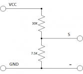
Note that arduino cannot handle >5V so we must use 2 resistors to make a suitable voltage divider. Using a 30k and a 7k5 resistor would be suitable.
The program above becomes a little more complicated, but not much:
Disclaimer: I do not have an ACA and have not built this spike-diverter (yet).
, so I hope you will forgive me for using a digital rather than analog attempt to solve the problem.The problem, as I see it, is that you do not want output to the speakers during unstable phases. In other words, you only want output when (you know) there is stability.
With little theoretical electronics knowledge, I assume that a suitably low-ohm high-power resistor parallel to the speaker will provide an alternative path for the spike and make it inaudible. Left in place, this resistor would also make our music inaudible, so we only want the resistor to be connected to the circuit during the unstable phases.
According to the simulations in posts 1 and 2, spikes occur during start-up (ca. 2 sec after power is switched on) and during shutdown (it takes about 200ms for the supply voltage to drop from 24V to 0V; in the simulation the spike occurs when voltage has dropped from 24V to 15V).
When I started working in software, computer were expensive. Nowadays, a small arduino computer (credit card sized) costs next to nothing (€ 2.50 from Aliexpress, including shipping). It is powered by 7-20VDC (it has its own inbuilt regulator to drop this to 5VDC). By placing a few diodes (under € 1 for a lot of 100 from Aliexpress) in series with the ACA PSU, the voltage can be brought down to under 20V, so no extra power source is needed to power the arduino. A suitable 24V relay could also come from Aliexpress for under € 1.
If the resistor is placed into the ACA output circuit as shown below, the resistor is always in the circuit unless the relay is turned on. We now need a program that will leave the relay off for a few seconds after powerup.
Although programming can seem difficult, programming an arduino is easier than learning LTSpice! The example below takes care of the start-up thump:
Code:
// Switch relay on 3 after seconds after startup
// Relay switching signal (+5V) is provided on digital pin 8

void setup()
{
  // setup digital pin 8 for output
  pinMode(8, OUTPUT);

  // make sure the relay is off by forcing the pin low
  digitalWrite(8, LOW);

  // wait for the power supply to stabilise, so do nothing for 3s
  delay(3000);

  // turn relay on
  digitalWrite(8, HIGH);
}

void loop()
{
   // we have nothing to run here
}
The powerdown thump is slightly more difficult. We need to make sure that as soon as the voltage drops (let's say below 22V but before it reaches 15V) the relay is turned off.
The arduino also has analog pins that can measure voltage. We can continuously measure the psu voltage and switch off the relay when the voltage drops below a set value.
Note that arduino cannot handle >5V so we must use 2 resistors to make a suitable voltage divider. Using a 30k and a 7k5 resistor would be suitable.
The program above becomes a little more complicated, but not much:
Code:
[FONT=Courier New][FONT=Courier New]// Switch relay on 3 seconds after startup
// Monitor voltage and switch relay off when voltage < 22V
// Relay switching signal (+5V) is provided on digital pin 8
// Voltage measurement using analog pin 1

void setup()
{
  // setup digital pin 8 for output
  pinMode(8, OUTPUT);

  // make sure the relay is off by forcing the pin low
  digitalWrite(8, LOW);

  // setup analog pin 1 for input
  pinMode(A1, INPUT);

  // wait for the power supply to stabilise
  // do nothing for 3 seconds
  delay(3000);

  // turn relay on
  digitalWrite(8, HIGH);
}


void loop()
{
  // The analog pin provides a digital value of 0-1024 for 0-5V
  // Our voltage divider reduced the voltage by a factor 5
  // To work out what the measured voltage is we multiply by 5
  // and divide by 1024

  // check voltage and turn the relay off when it is low
  if (analogRead(A1) * 5.0 / 1024) < 22)
    digitalWrite(8, LOW);

  // we now wait for the power to drop low enough so the arduino is
  // switched off due to lack of power
  while(true)
    delay(1000);
}[/FONT][/FONT]Attachments
Last edited:
They say a carpenter thinks with his hammer. More generally, you solve a problem with the tools you are used to. After more than 35 years of writing software I think you can appreciate what my hammer looks like
Thanks Albert
Using a uP based approach is pretty much alien to me (my programming skills might just about reach to getting an LED to flash given enough time) but I agree its a valid approach for those that can make it work.Albert, that is 'my type of hammer' also!
I have been contemplating something similar to create the standard 12V trigger on the ACA.
Wouldn't you be afraid that the 'noisy' arduino could affect the highly-sought-after clean supply?
As for the trigger, I will not hijack this nice initiative with any details, this is just form thumps and weeeeeps.
Rafa.
Use the NC contacts of an SPDT or DPDT relay, to connect a 1 ohm resistor in parallel with the speaker terminals. Arrange the relay to pull-in "X seconds" after power on, which disconnects the 1 ohm resistor from the speaker terminals.
This shrinks the output thump by a factor of nine. 8/9ths of the thump goes into the 1 ohm resistor, and 1/9th of the thump goes into the 8 ohm loudspeaker.
You could imagine different choices of resistor value too.
This shrinks the output thump by a factor of nine. 8/9ths of the thump goes into the 1 ohm resistor, and 1/9th of the thump goes into the 8 ohm loudspeaker.
You could imagine different choices of resistor value too.
Use the NC contacts of an SPDT or DPDT relay, to connect a 1 ohm resistor in parallel with the speaker terminals. Arrange the relay to pull-in "X seconds" after power on, which disconnects the 1 ohm resistor from the speaker terminals.
This shrinks the output thump by a factor of nine. 8/9ths of the thump goes into the 1 ohm resistor, and 1/9th of the thump goes into the 8 ohm loudspeaker.
You could imagine different choices of resistor value too.
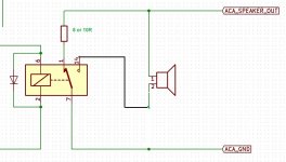
Then why not do it this way? 8R to charge C1 once 'stable' the relay pulls and swaps to the speaker. Better still if one could make the relay pull in at switch on and drop once stable, then it would 'fail safe'.
Attachments
- Status
- This old topic is closed. If you want to reopen this topic, contact a moderator using the "Report Post" button.
- Home
- Amplifiers
- Pass Labs
- A possible approach to adding a silent start/shutdown to the ACA