Bias... as in the midpoint adjustment setting.
The midpoint voltage should rise and fall at the same rate for both amps and if it does then that means no difference in voltage exists between the two separate amplifier outputs. In practice that probably wont happen due to tolerances in caps and the semiconductors. Hopefully it will be fairly quiet though.
The midpoint voltage should rise and fall at the same rate for both amps and if it does then that means no difference in voltage exists between the two separate amplifier outputs. In practice that probably wont happen due to tolerances in caps and the semiconductors. Hopefully it will be fairly quiet though.
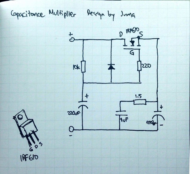
One way that I prevent turn on thump in almost any amplifier is to use a cap multiplier with a slow ramp up of output voltage. So in addition to providing ripple reduction of the power supply, it never has thump for turn on or off.
Pretty simple circuit (replace IRF610 with IRFP240 for higher currents) - this is design I got from Juma. I use this in almost all of my single rail amps now.
Pretty simple circuit (replace IRF610 with IRFP240 for higher currents) - this is design I got from Juma. I use this in almost all of my single rail amps now.
first of all, it's christmas time and i am a non electrician, so please be patient ")
I am just working on a ACA
Not the original one, but another one, also described here which has an old style PSU with a LM1084 voltage regulator.
Having no pops and also the advance of a cap multiplier makes me curious.
The situation is now that i have a bridge rectifier followed by the regulator.
First thing on the PCB is a 4700µF cap
Can i just plug off the rectifier and pull in that little circuit before the regulator?
I suppose that would be what i can handle with my limited skills
Can i 'recycle' the 4700µF cap on the regulator as C7 of the cap multiplier?
Best without screwing up the cap multiplier or the regulator
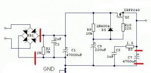
I have downloaded the Juma sheme and tried to mark what i think to do (see pic)
thanks Joachim
I am just working on a ACA
Not the original one, but another one, also described here which has an old style PSU with a LM1084 voltage regulator.
Having no pops and also the advance of a cap multiplier makes me curious.
The situation is now that i have a bridge rectifier followed by the regulator.
First thing on the PCB is a 4700µF cap
Can i just plug off the rectifier and pull in that little circuit before the regulator?
I suppose that would be what i can handle with my limited skills
Can i 'recycle' the 4700µF cap on the regulator as C7 of the cap multiplier?
Best without screwing up the cap multiplier or the regulator
I have downloaded the Juma sheme and tried to mark what i think to do (see pic)
thanks Joachim
Attachments
Last edited:
I can't quite follow what you are trying to do in particular 'plugging off the bridge rectifier'.
For a conventional power supply you need in order from left to right, the bridge rectifier and suitable reservoir cap (47,000uF in your diagram which seems a bit big tbh). Then you could add the cap multiplier and following that your original regulator.
You need to ensure the regulator still has enough voltage to work with once the multiplier is added.
in particular 'plugging off the bridge rectifier'.For a conventional power supply you need in order from left to right, the bridge rectifier and suitable reservoir cap (47,000uF in your diagram which seems a bit big tbh). Then you could add the cap multiplier and following that your original regulator.
You need to ensure the regulator still has enough voltage to work with once the multiplier is added.
I can't quite follow what you are trying to do
that's because i am trying to explain things i do not know about in an language i did not speak
in particular 'plugging off the bridge rectifier'.
the regulator and the ACA are both on the same PCB.
The rectifier is mounted on the case.
What i want to ask is where the right place for the cap multiplier is.
Between the regulator and the ACA or before the regulator.
The later one would be easy to handle.
Now i know. I will try to build that thing.
Of course C1 is way to big, it was only thought as an example.
I will read thte article i have stolen the pic from
Thanks for the advice with the voltage
reagrds Joachim
For a conventional power supply you need in order from left to right, the bridge rectifier and suitable reservoir cap (47,000uF in your diagram which seems a bit big tbh). Then you could add the cap multiplier and following that your original regulator.
You need to ensure the regulator still has enough voltage to work with once the multiplier is added.[/QUOTE]
A cap multiplier added after a regulator will totally negate the final 'voltage regulation' of the regulator.
In other words the final voltage from the multiplier will vary with current drawn from the supply due to the finite impedance of the multiplier. That may or may not matter to you in this application.
Adding the multiplier before the regulator allows for increased ripple reduction (a good thing).
(Also remember that most voltage regulators like the LM1084 should not work into to large a capacitive load, 47 uF to 100uF is usually all that is required)
Which is exactly the mistake Teddy Pardo made in the SuperTeddy Regulator. He connected the VR first ("upstream") and the CM second ("downstream") Oops!
Here is a link: SuperTeddyReg | DIY | TeddyPardo
Here is a link: SuperTeddyReg | DIY | TeddyPardo
I was also thinking along the old and cranky lines. A FET does give at least 4 volts loss though, so maybe a BJT is better suited slooking at voltage drop and internal resistance. The result is that you can suse a 24V LED rail SMPS they cost only several bucks.
There have been several designs with a FET in the power rail (Broskie comes to mind where he used it as insurance).
My other thoutht is: why not go from SE coupling (one cap) to double cap (one to the plus, the other to the minus, AFTER the speaker. So the two caps become the virtual ground.
Then these caps can have a resistance in series to load them. 150-1000 ohms?
Maybe have that relay CVC across that?
View attachment ACA1 virtual ground.asc
My less than 2¢
An unusual idea
A FET rail switch needn't be lossy. A P channel FET to switch a positive rail will only give a loss dependent on the Rds value and the load current. So absolutely minimal loss and power dissipation, even at several amps of load current.
I'm not sure on the cap idea... the rate at which the ACA output settles to 12 volt and the rate at which the caps virtual ground voltage settle will not be equal, and that will still generate a noise. You have to keep churning ideas around though
An unusual idea
A FET rail switch needn't be lossy. A P channel FET to switch a positive rail will only give a loss dependent on the Rds value and the load current. So absolutely minimal loss and power dissipation, even at several amps of load current.
I'm not sure on the cap idea... the rate at which the ACA output settles to 12 volt and the rate at which the caps virtual ground voltage settle will not be equal, and that will still generate a noise. You have to keep churning ideas around though
You are right. I was bound with my thought the Vgate needed to come from the power rail itself.
The two caps solution - often used in power amps to ensure zero DC load & - I am also using this idea in a MC amplifier.
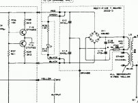
If you are interested in the virtual ground arrangement then have a look at the Quad 606 power amp. That is a 'DC coupled' amp using the junction of two series connected reservoir caps in the power supply as a virtual ground. The Quad achieves the correct DC balance between the caps not with resistors but with two small signal transistors.
Attachments
... {in a conventional capacitance multiplier circuit} a FET does give at least 4 volts loss though, so maybe a BJT is better suited slooking at voltage drop and internal resistance. The result is that you can suse a 24V LED rail SMPS they cost only several bucks.
Since ACA uses a single ended positive supply, you can build your capacitance multiplier with a "JFETlington" pass transistor, which uses the still-active-production J105 or J107 Nchannel JFET. (deep depletion PJFETs are out of production but ACA has no negative-voltage power supply). And thereby get very low input-to-output "dropout" voltage.
Because there's no base current into the JFET, you can use a high value bias resistor (unlike a BJT cap multiplier) and thus get filtering with a very low corner frequency. Because the JFET operates with its gate voltage significantly less than its source voltage, you can conveniently arrange a simple resistive divider with a multiturn trimmer pot, allowing you to slooooowly dial in the exact voltage drop you desire.
It's all thru-hole, it's all on the shelf and available at Mouser or DigiKey.
The two caps solution - often used in power amps to ensure zero DC load & - I am also using this idea in a MC amplifier.
Forgetaboutut.
In the mean time I ran the simulation (zener is 22v, not in my database; had to use 10+12V); and I used 2SK170. There is a large plop in the output.

I'd bet you could even dispense with the timer and just use a single FET + R & C to drive the couplers.
Yeah, I originally did try that, but to minimize switching times to keep the MOSFET's power dissipation at the switching transition to a minimum, I decided to go with the 555. I've never had any problems, and in many years of use it's been 100% reliable.
Mike
- Status
- This old topic is closed. If you want to reopen this topic, contact a moderator using the "Report Post" button.
- Home
- Amplifiers
- Pass Labs
- A possible approach to adding a silent start/shutdown to the ACA