From David @ Cinemag, they are doing a production run now of CMOQ-4HPC, so they will be shipping soon.")
Thanks for info. I'm waiting too


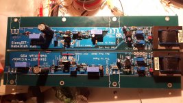
open these red jumpers , if you didn't already set buffers
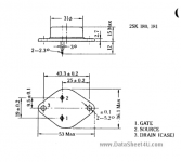
do you know Ugs for your 2SK180 , for Iq in range of 1A8-2A ?
of course that you need to find a way of mounting 2SK180 - use piece of L bracket , no lesser thickness than 5mm
take care that "flying" gate resistor is near gate pin of 2SK180 ; good practice is to heatshrink it with wire , that way it's sturdier
naturally......you explained it clear...but...I do not want to miss the jumpers .... I left them for thisopen these red jumpers , if you didn't already set buffers
no.....but maybe I can find it in the documentation I havedo you know Ugs for your 2SK180 , for Iq in range of 1A8-2A ?
I already have a 4mm L bracket available.of course that you need to find a way of mounting 2SK180 - use piece of L bracket , no lesser thickness than 5mm
good practicetake care that "flying" gate resistor is near gate pin of 2SK180 ; good practice is to heatshrink it with wire , that way it's sturdier
thanks a lot ZM...my master
Last edited:
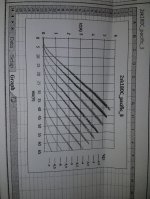
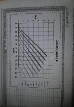
characteristic curves obtained from Jama instrumentally supplied by SIT in attach.
In any case if you can give me a link where I can find the correct procedure I thank you ..... but I ask you: how should I then do the calibration?
In any case if you can give me a link where I can find the correct procedure I thank you ..... but I ask you: how should I then do the calibration?
Attachments
i saw D1+D2 being stuffed on your boards, and I remember them as leftouts in the Sissy circuit,
but wait for the Pros to respond on this, I´m troublemaker chicken : )
"..... but I ask you: how should I then do the calibration?"
you don´t do calibration, it´s just for veryfying that Sit is within (optocoupler?) window
but wait for the Pros to respond on this, I´m troublemaker chicken : )
"..... but I ask you: how should I then do the calibration?"
you don´t do calibration, it´s just for veryfying that Sit is within (optocoupler?) window
Last edited:
It's true .... not careful.i saw D1+D2 being stuffed on your boards, and I remember them as leftouts in the Sissy circuit,
In the scheme of the Sissy D1 and D2 are omitted. I provide for the removal.
Many thanks mate
characteristic curves obtained from Jama instrumentally supplied by SIT in attach.
In any case if you can give me a link where I can find the correct procedure I thank you ..... but I ask you: how should I then do the calibration?
according to these graphs , so I understood they're exact measurements of your specimens , it seems that they're in region of -3 to -3V5 for our range of voltage and currents
so , just go for it
regarding surplus diodes - just cut their pins
thanks ZM
I had been content to see that based on those curves I was in the right range.
But making the measure at home is certainly not wrong especially if you do not know anything about the components in your hand.
However, what is the exact bias procedure to run the static current around 1.8 - 2A?
I had been content to see that based on those curves I was in the right range.
But making the measure at home is certainly not wrong especially if you do not know anything about the components in your hand.
However, what is the exact bias procedure to run the static current around 1.8 - 2A?
in practise you cut negative wire from PSU, put 0,1R in between, there you measure across 180 to 200mV. But starting cold set it no higher than approx 150mV, it will rise significantly over half an hour so so. After Iq being stable do fine adjustment for offset.
(maybe all was clear to you : ), doesn´t hurt to write again, anyway)
Iq pot for beginning set as in schematic!
(maybe all was clear to you : ), doesn´t hurt to write again, anyway)
Iq pot for beginning set as in schematic!


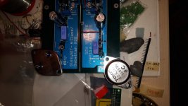
I have currently an F4 with CRC PSU with 8x27000u/50 Panasonic 105º TSHA
I intend to use this for my Sissy Sit but with dual mono operation with 2 250VA trannies and new psu boards.
I would buy more of the same caps but AFAIK they are no longer being available.
Assume I should I spread the caps over all 4 new boards and add something similar in remaining two 'slots' per board . I believe they are good caps. What would be a good match for optimum SQ? I could try to match specs but welcome any recommendations.
I imagine with dual 250VA supplies the 27mF caps are more of an overkill and I could add somewhat smaller capacity items.
Last edited:
- Home
- Amplifiers
- Pass Labs
- SissySIT