Back from Eywa
pras , you did it pretty much in good way , but you need to correct one thing immediately:
use much bigger heatsink and be sure that THF (or 2SK) is properly bolted to heatsink , to ensure good thermal transfer between SIT and heatsink body
to repeat few things :
- PSU for drain - everything from 19Vdc to 24Vdc is OK for testing purposes
-I expect that all SITS having Ugs in range from -1V to 3V6 (or even -4V if we select mating mosfet for higher Ugs) will work in SissySIT circuit
-measure either for 1A8 or 2A of drain current ; no need to measure both values
Back from Eywa
pras , you did it pretty much in good way , but you need to correct one thing immediately:
use much bigger heatsink and be sure that THF (or 2SK) is properly bolted to heatsink , to ensure good thermal transfer between SIT and heatsink body
to repeat few things :
- PSU for drain - everything from 19Vdc to 24Vdc is OK for testing purposes
-I expect that all SITS having Ugs in range from -1V to 3V6 (or even -4V if we select mating mosfet for higher Ugs) will work in SissySIT circuit
-measure either for 1A8 or 2A of drain current ; no need to measure both values
hi
Are you back?
Would you please be clear about my test?
measure either for 1A8 or 2A of drain current ; no need to measure both values
What do Imean by that
1. use BIG HEATSINK and screw or bolt or clamp SIT to it
2. measure at 2A ; no need to measure at 1A8
3. everything else you did is OK
*1. use BIG HEATSINK and screw or bolt or clamp SIT to it
What size of radiator do you need? I need to buy a piece of what size (what size).
Then do this, is it meeting your requirements?
Bolt properly to the radiator to ensure good heat transfer between the seat and the radiator body
Need to screw his ears to the radiator?
So every time I test it, it's a hassle, because I need to test one and then test another (so I don't have to install a screwdriver radiator yet).
Need to screw his ears to the radiator?
So every time I test it, it's a hassle, because I need to test one and then test another (so I don't have to install a screwdriver radiator yet).
*1. use BIG HEATSINK and screw or bolt or clamp SIT to it
What size of radiator do you need? I need to buy a piece of what size (what size).
Then do this, is it meeting your requirements?
see here , post #608 : Most Greedy Boy, of them all... or (there is no) DEFiSIT of Papa's Koans
..........
Need to screw his ears to the radiator?
So every time I test it, it's a hassle, because I need to test one and then test another (so I don't have to install a screwdriver radiator yet).
yes , be creative - either screw it's ears to heatsink , or clamp it somehow
you can use screws with big washers , then just place ears of SIT beneath washers and tighten the bolts..... faster that way
it is a hassle , but who said that everything in life is quick and easy
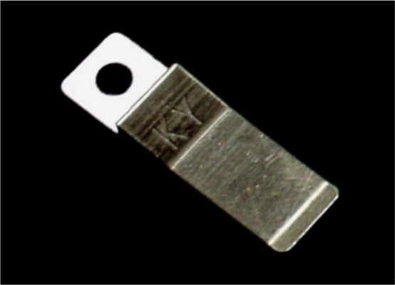
pic of spring clamp, you'll need two :
Clamp THF-51 is a great solution! Save a lot of efforts and time ")
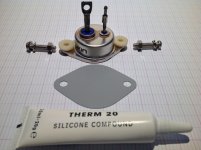
What about clamps and drain case electrical isolation by mica or thermal pad
( cheap relay one or expensive keratherm ) and goop thermal paste ?
Perfect in case heat sink is made in raw not anodized aluminium.
Cook every SIT for 10~15 minutes on the heatsink before test can give more precise mesurements. What You think Diyers ?
Attachments
for testing - I wrote already about that but who knows in which of related threads , there is no need for any thermal interface
for final placing of SIT - that thing is so damn big , considering 50W of heat in Sissy circuit - even 0.1mm thick mica plus grease is more than good enough
for final placing of SIT - that thing is so damn big , considering 50W of heat in Sissy circuit - even 0.1mm thick mica plus grease is more than good enough

if you're asking what's happening when operator is dumb as Dodo ....... I made all possible mistakes already , repetitively , so I can leave SIT connected with heatsink when testing .... avoiding heatsink with everything on different potential
if someone is chickened with that , electrical isolation between heatsink and DUT is wise
if someone is chickened with that , electrical isolation between heatsink and DUT is wise
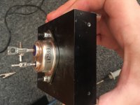
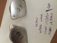
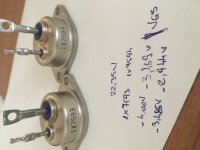
Having some free time today I decided to take a look at the vgs of my fets at 2 values of drain current that interest me. These values are 2a and 3.2a
As can be seen in the pictures I have attached the dut on a small heatsink and measured vgs when the heatsink was at 45c. Drain voltage was 22.35v
When bought from tomo he said that they are matched at 2a drain current and 20-25vds and have -1vgs.
Now on the fets are other values written down than those he mentioned when selling them and when testing them today I found different values from those written on them/mentioned in the sale.
Is there anyone else who noticed this on their fets from tomo?
Sorry for the flipped photos can’t manage to make them show right when uploading from the phone.
Attachments
yes , be creative - either screw it's ears to heatsink , or clamp it somehow
you can use screws with big washers , then just place ears of SIT beneath washers and tighten the bolts..... faster that way
it is a hassle , but who said that everything in life is quick and easy
pic of spring clamp, you'll need two :
I understand, the radiator needs to be so thick, so big.
I will buy a radiator in the store tomorrow, and drill 2 holes on the radiator according to the ear distance of the THF-51S. Is the result of the measurement different?
Sometimes convenient to use
Also buy a few turnbuckles
Having some free time today I decided to take a look at the vgs of my fets at 2 values of drain current that interest me. These values are 2a and 3.2a
As can be seen in the pictures I have attached the dut on a small heatsink and measured vgs when the heatsink was at 45c. Drain voltage was 22.35v
When bought from tomo he said that they are matched at 2a drain current and 20-25vds and have -1vgs.
Now on the fets are other values written down than those he mentioned when selling them and when testing them today I found different values from those written on them/mentioned in the sale.
Is there anyone else who noticed this on their fets from tomo?
Sorry for the flipped photos can’t manage to make them show right when uploading from the phone.
Yes, I have different Vgs too. See my posts #266, 273, and 287.
Testing at Vgs=-1V does not seem to be a good thing to do. Depending on the SIT, it may draw a very high current through it. I suspect that his power supply may not be able to provide the current capacity so that is why he is able to test at Vgs=-1V.
I am still waiting for a reply to my latest message that I sent him.
I’m glad I have other projects going on and that I will force myself to wrap them up before starting this one...but you guys are making me a little anxious to set up a test rig and see what I got from watanabe.
I know Zen said we don’t have to worry about thermal isolation during testing as long as we are careful, but I was interested in covering that detail for when I got started. I was looking in the other Hockey Puck thread where these THF51S were being discussed as I remember Soundhappy posting a pad solution in the form of a large relay pad from MPJA. Well, they’re NLA according to the site. The pads the DIY store sells are too small. Anyone else come up with an easy/cheap solution?
I know Zen said we don’t have to worry about thermal isolation during testing as long as we are careful, but I was interested in covering that detail for when I got started. I was looking in the other Hockey Puck thread where these THF51S were being discussed as I remember Soundhappy posting a pad solution in the form of a large relay pad from MPJA. Well, they’re NLA according to the site. The pads the DIY store sells are too small. Anyone else come up with an easy/cheap solution?
As long as the heatsink is electrically isolated, the SIT can be placed directly on the heatsink for testing. Although I used thermal compound between my SITs and heatsink, that is probably not necessary as long as the SIT is bolted securely to the heatsink for good thermal contact. I did not use any isolation pad. Just make sure that the heatsink is not in contact with any other parts of the test circuit.
- Home
- Amplifiers
- Pass Labs
- SissySIT