Just wondering....Am I only one building this version? Finishing other projects first but I see many going for SissySit version, not much activity with M25.
I have every intention to build both, but given MOST, (not all) my speakers are fairly easy to drive, I am thinking about starting with Sissy sit version as first build. (As in before M25, way to late for "first" build)
Any other M25 builders out there?
Russellc
I have every intention to build both, but given MOST, (not all) my speakers are fairly easy to drive, I am thinking about starting with Sissy sit version as first build. (As in before M25, way to late for "first" build)
Any other M25 builders out there?
Russellc
several B. M25 kits sent , but will they end as SissySIT ....... I can't tell ...... I mean - guess
I know that soon I'll have both fully made , as proper and complete amps , of my own!
contrary to earlier ones ....... I never finished my own specimens of Babelfish J , nor Babelfish J2

I know that soon I'll have both fully made , as proper and complete amps , of my own!
contrary to earlier ones ....... I never finished my own specimens of Babelfish J , nor Babelfish J2
I have been listening to commercial First Watt M2. Because it has been such a shape shifter for me, I have been playing around with the strictly subjective aspects. At times, it is brilliant in wholistic, organic way but needs to be left on for a while to get this for some reason.
Anyway, with ribbon speakers, M2 works well down to 2.5R. However, it sounds better with 4R ribbon, but really locks in in sound quality at 8-10R using an impedance matching transformer. So at least with my speakers, it just sounds most optimal at the 8 and above impedance level, though it is quite good also at the lower impedances.
Want M2 to sound 'spooky' like VFET, with that special luminescence and gilded emergence from space, while still having the PRAT organic thing of M2? Use a directly heated triode driver/preamp.
I don't know why this would be, but it is special sounding. VFET doesn't need this and can sound 'spooky' on it's own or with a transistor preamp.
Maybe adding the second order harmonics from the tube to the more dynamic sounding, driving third order harmonic from the MOSFETs in M2 does something, but this, or course, is daft speculation with no objective foundation. The particular DHT tube is a tube rectified 26 tube. I would imagine many DHT tube drivers might give a similar result.
This is why I want to attempt my first DIY with the Korg B1 project (aside from it looking like an entry level project even I can tackle). I am curious how the Korg NUTUBE driver will effect the M2 sound compared to my VFET amps/or directly heated triode drivers with M2.
Last edited:

Any other M25 builders out there?
Russellc
I'm going also for M25 as soon as I get kit from ZM. I have built M2x so wanna try CineMag this time.
I ordered directhly from CineMag. Took awhile before I got an answer. Have now ordered and paid and waiting "patiently"Oh, do you have any idea when they are available? And where?")
for delivery.Contact Cinemag Inc.
I ordered directhly from CineMag. Took awhile before I got an answer. Have now ordered and paid and waiting "patiently"
Contact Cinemag Inc.
Thanks alot! I will contact them
I had ordered a pair of Cinemag CMOQ-4HPC (the high-Nickel version) mid-November.
Just got the shipping notice earlier tonight.
Had talked to David at Cinemag on the phone last week to inquire about the status. He said they had been backed up because of the holidays and a big order from Pass Labs ...
Best regards,
Claas
Just got the shipping notice earlier tonight.
Had talked to David at Cinemag on the phone last week to inquire about the status. He said they had been backed up because of the holidays and a big order from Pass Labs ...
Best regards,
Claas
Has anyone else, apart from ZenMod, successfully implemented the M25 amp?
I made my own PCBs only for the Output stage, without the input stage and audio transformer. Set current to 1.4A and before I could back off the Iq, the IRFP240 on the positive rail, went up in smoke.
Prior to the Mosfet giving up the ghost, it did hold well upto 500mA for several minutes with 10E 5W resistors on both rails and offset could be set to less than 10mV.
Any thoughts, comments or instructions from anyone? Of course, Mighty ZenMod would have more to say. Thank you.
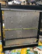
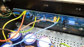
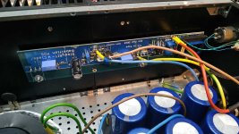
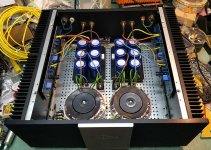
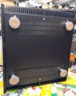
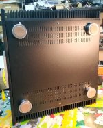
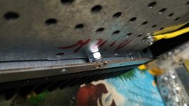
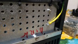
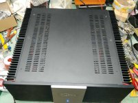
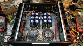
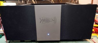
finished just yesterday another one , sorta Chameleon or Convertite amp
was F4 in first instance , not made by me
then I converted it to Babelfish J , funny - additional front panel engraved to Babelfish J2 due to miscommunication between owner and guy who made the plate
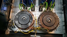
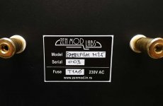
now , hope finally, converted to Babelfish M25 , also changing from common PSU to proper dual mono
was F4 in first instance , not made by me
then I converted it to Babelfish J , funny - additional front panel engraved to Babelfish J2 due to miscommunication between owner and guy who made the plate
now , hope finally, converted to Babelfish M25 , also changing from common PSU to proper dual mono
Attachments
-
 IMG_20190124_191951.jpg176.2 KB · Views: 372
 -
 IMG_20190124_193458.jpg90 KB · Views: 147
 -
 IMG_20190124_193448.jpg78.6 KB · Views: 146
 -
 IMG_20190124_193442.jpg111.3 KB · Views: 138
 -
 IMG_20190124_193437.jpg89.4 KB · Views: 174
 -
 IMG_20190124_193429.jpg159.1 KB · Views: 173
 -
 IMG_20190124_192847.jpg130.7 KB · Views: 386
 -
 IMG_20190124_192836.jpg177.6 KB · Views: 373
 -
 IMG_20190124_192006.jpg43.1 KB · Views: 381
 -
 IMG_20190124_191959.jpg60 KB · Views: 371
.....
Prior to the Mosfet giving up the ghost, it did hold well upto 500mA for several minutes with 10E 5W resistors on both rails and offset could be set to less than 10mV.
.......
in Babelfish M25, SissySIT - general building tips and tricks , I'm specifically saying that you use 0R1 in negative rail for monitoring Iq , more important to be in neg rail for Sissy , of course
though , if one is using CRC filter in PSU , Iq can be monitored on R in CRC , so no need for additional 0R1 , inserted temporary in neg rail
so , you said 10R ??
Last edited:
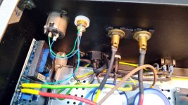
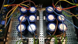
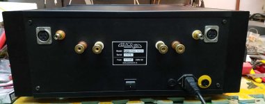
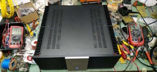
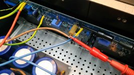
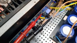
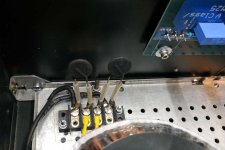
more of Convertite
Attachments
-
 IMG_20190124_201641.jpg42.1 KB · Views: 111
 -
 IMG_20190124_195402.jpg102.4 KB · Views: 95
 -
 IMG_20190124_195350.jpg112.7 KB · Views: 116
 -
 IMG_20190124_194506.jpg83.6 KB · Views: 100
 -
 IMG_20190124_194500.jpg85.3 KB · Views: 119
 -
 IMG_20190124_194453.jpg145.8 KB · Views: 125
 -
 IMG_20190124_194408.jpg34.2 KB · Views: 122
 -
 IMG_20190124_193521.jpg70.3 KB · Views: 109
 -
 IMG_20190124_193506.jpg109.1 KB · Views: 143
 -
 IMG_20190124_201652.jpg51 KB · Views: 122
Has anyone else, apart from ZenMod, successfully implemented the M25 amp?
I made my own PCBs only for the Output stage, without the input stage and audio transformer. Set current to 1.4A and before I could back off the Iq, the IRFP240 on the positive rail, went up in smoke.
Prior to the Mosfet giving up the ghost, it did hold well upto 500mA for several minutes with 10E 5W resistors on both rails and offset could be set to less than 10mV.
Any thoughts, comments or instructions from anyone? Of course, Mighty ZenMod would have more to say. Thank you.
Just to add to the quoted post, I followed the schematic in post #118. Rails were 24.46 volts regulated. Thank you.
- Home
- Amplifiers
- Pass Labs
- Babelfish M25, AKA M2 on steroids, AKA M2-XA25 bstrd AKA M2 gone Berserk