I'm glad to see the three/four way pcbs are finally coming out!! Will there be unbalanced versions available for those of us who don't require balanced outs?
There is a single-ended 3-way on my to-do list which is hard-wired for the
3 different versions.
These plugs fit into the case cutouts
unbalanced
http://www.neutrik.de/de-de/cinch/cinch-einbaubuchsen/
or balanced
NC3FD-V | Neutrik
NC3MD-H | Neutrik
Nelsons existing board has dedicated connections for either type
unbalanced
http://www.neutrik.de/de-de/cinch/cinch-einbaubuchsen/
or balanced
NC3FD-V | Neutrik
NC3MD-H | Neutrik
Nelsons existing board has dedicated connections for either type
I have questions regarding a volume control in front of my lxmini crossover:
- In a first trial 10k potentiometer in front of the circuit works, but with a nominall 10k input impedance it is not ideal because the current gets shared between crossover and potentiometer. Should one use a buffer in front of the crossover, or are there other options?
- There used to be a buffer in front of the crossover (see Linkwitz lab site and other thread on diyaudio). Why was it omitted in the final version? Is there a chance to buy the matched transistors and resistors tuned to the sweet spot separately somewhere to build one more buffer? Putting a B1 buffer in fron seems a bit overkill, and using the same buffers as in the crossover seems reasonable to me.
- Is there any chance one can do this without a distortion analyser? There a cheap transishor testers around wich can match the devices, but could they be used to find the resistors for load line cancellation?
- what resistance values should a potentiometer (or one of the cheap stepped attenuators) in frong lf a buffer have? What value should a passive volume control potentiometer without buffer have?
Thanks
Last edited:
A buffer is ideal, but if you use the potentiometers as shown, you will find that
the differences are slight. The design is set so that if you have amps
with equal gain, you can turn both pots up so that the filters see the
impedance of the source. Testing the influence of the pots at worst case
settings, we still get good results.
All of this assumes that your source can drive 10 Kohm. If not, then
a buffer would be a good idea, but you should try it without first.
After reading the article and the thread, and briefly tried the simulation, I can allow myself three silly questions.
1. How do you remove the EQ part? I have a Minidsp 10x4Hd and never used the EQ anyway.
2. Can I just add a second PCB board and split the left and right input to get a 4-way crossover? Wouldn't that remove a lot of the signal strength?
Signal strength is why I dislike Minidsp, because it removes so much of it. If I then add another DSP like Dirac room correction the music is too anemic.
3. What happens with polarity with four stereo channels with 12dB/octave? Which speaker channel need inverted polarity?
1 The Eq part is a separate circuit in series, so you can just bypass it.
2 A second pc board will give you a three way crossover, as you generally
have a low pass and a high pass for the midrange, which uses up two filters.
3 Most commonly you invert the polarity with each successive crossover, for
example woofer+, midbass-, midrange +, tweeter- (or vice versa) This is not
a fixed rule, as driver response sometimes calls for something else.
Buy a copy of Tube Cad Filter Designer software - it's only $10 - no math!Ok, thanks! I had a quick look at the simulation in MicroCap but I could not see an easy way to change adjust the crossover points. Do I need a copy of the 500 page book on active crossovers?
TCJ Filter Design - Download
Last edited by a moderator:
I am not sure what to now. Buy three boards and hope that I can throw together advanced filters from nothing? :S
I will give TCJ a try!
Here is how I use TCJ to design for the buffered LX-mini board:
1) Choose Active Solid State, HP or LP, set frequency, 2nd Order, Display Values, Linkwitz-Riley alignment
2) re: Display Values - note, this tab area may sometimes reset filter to Bessel, so watch out and you may need to change it back to L-R which in 2nd order L-R always has the two caps and the two resistors equal in value
3) Change the cap values to the closest standard value. Resistors will update automatically and can then typically be rounded up or down in Micro-Cap or LT Spice (not in TCJ) to the closest standard value as well.
4) If TCJ acts weird regarding any values or settings, I close the program, reopen it and start over. Sometimes the program is sensitive to the order you use to make configuration or value choices and it screws up.
5) Model the circuit to verify crossover frequencies and slopes. It is easy to delete the low and high EQ sections in the LX-mini models, leaving just the 2nd order portion of the circuit.
6) If you need 3 or 4 filters you can re-purpose the EQ portions of the board by cutting traces, adding jumpers and changing caps to resistors, etc, as needed.
That is really helpful, thanks.
My other issue is that I have a 5-way horn system with three channels that require bandpass at 65-500Hz, 500-1500Hz, 1500-3000Hz. Tweeter needs 3000Hz and up. Subwoofer needs 30-80Hz 4th order, but in worse case I can use another filter for that. Question is, do I split the signal at source or cascade as many LXmini as it is required from the output of the previous LXmini.
Should I just wait for the B4 mkII to come out, but will that help me at all since I have so many channels?
And why did Papa recommend me not to use the EQ with so many channels?
Last edited:
That is really helpful, thanks.
My other issue is that I have a 5-way horn system with three channels that require bandpass at 65-500Hz, 500-1500Hz, 1500-3000Hz. Tweeter needs 3000Hz and up. Subwoofer needs 30-80Hz 4th order, but in worse case I can use another filter for that. Question is, do I split the signal at source or cascade as many LXmini as it is required from the output of the previous LXmini.
Should I just wait for the B4 mkII to come out, but will that help me at all since I have so many channels?
And why did Papa recommend me not to use the EQ with so many channels?
I would not cascade boards, I would parallel inputs to multiple boards, using all-pass buffers if necessary. I think you can do this with two LX-mini crossover boards if you want all 2nd order filters. To do that, both boards will require some rewiring, jumpers, etc. to also use the EQ sections as either HP or LP sections. Perhaps Papa said not to use them to avoid cutting traces, adding jumpers and putting capacitors in resistor spaces and resistors in capacitor spaces but they are not really difficult circuit board hacks if you look at the schematic requirements.
LX-mini board is just JFET buffers instead of OP-Amp or tube buffers. Using all of Board 1 would give you bandpass filter 1 and bandpass filter 2. Using all of Board 2 would give you bandpass filter 3, plus HP for the tweeter and possibly LP for the subwoofer but you would still be missing the 30Hz HP subsonic filter. For that you would need a 3rd board or just use the separate bandpass subwoofer filter you mentioned.
For one board, the two 25K input pots in parallel are a 12.5K load to the source. A second board with hardwired parallel inputs would make that 6.25K, getting a bit low but not unmanageable if your preamp or source has a low output impedance. My experience is that as long as you stay above 5K summed input impedance you are probably OK with a solid state source, although staying above 10K is safest.
Alternatively, if you use your separate subwoofer bandpass filter, you could re-purpose the unused section of board 2 as an all pass buffer to drive the inputs of the subwoofer filter.
Careful reading of Papa's notes shows his recommendation that trim pots be used wide open if possible. If your power amps have input attenuation, that would be a good experiment to see what sounds better for level balancing.
Another way to slice this pie is to use 3 stereo LX boards, all 3 in various stages of rewiring. Board 1 gives you the subwoofer bandpass plus bandpass 1. Board 2 gives you bandpass 2 and bandpass 3. Board 3 gives you the tweeter high pass plus 2 all-pass buffers to drive boards 1 and 2.
Is all this worth the bother? I think yes. I have only used the analog LX-mini crossover as an alternate to the miniDSP HD processor on an actual pair of stock LX-mini loudspeakers. Papa's circuit does sound better but it is hard to say if that is the smoother EQ curves, which have less phase shift, the higher 40Hz cutoff which reduces woofer cone over-excursion and distortion, more signal headroom in the JFETs vs the DSP processor, lower noise floor, lack of jitter inherent in DSP, or elimination of A/D then D/A in the DSP. I suspect all of the above.
A test that I have not yet done would be to model Papa's LX analog curves in the miniDSP and have a listen. I have tried bypassing the miniDSP HD analog input with a direct Toslink connection and did not think it helped. So for me, the JFET buffer circuit is the real winner so far in the active crossover world and I intend to build another using an LX board, customized for my other 500Hz biamped 3-way system.
For one board, the two 25K input pots in parallel are a 12.5K load to the source. A second board with hardwired parallel inputs would make that 6.25K, getting a bit low but not unmanageable if your preamp or source has a low output impedance. My experience is that as long as you stay above 5K summed input impedance you are probably OK with a solid state source, although staying above 10K is safest.
Thanks for taking the the time to write all that!
So if I need three boards, the load to the source is split again to 3.125K, which is too low? Then I don't see how I can use three LXmini boards, but I am probably missing something.
Last edited:
Thanks for taking the the time to write all that!
So if I need three boards, the load to the source is split again to 3.125K, which is too low? Then I don't see how I can use three LXmini boards, but I am probably missing something.
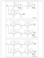
My concept is attached. It does require a lot of circuit board hacking. That is, cutting traces, adding jumpers, etc.
If you want to minimize board hacks and not use the HI EQ sections, you might also consider changing all the input trim pots to 100K, using 3 boards, 2 with only a bandpass filter and the other with a bandpass and a high pass for 3000HZ. You would need your external subwoofer crossover but as long as the input impedance was 25K or more you should be OK. You might be able to keep the input trims at 50K. Since the DIYstore only sells the boards with JFETs you would not be using almost half of them.
Attachments
After being unavailable for a while due to some logistics issues, the "Basic + LX Mini Kit" is on the shelves again, with immediate shipping.
Thanks again, will try to simulate this eventually.
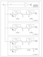
And here is how to do it with no board hacks required.
Attachments
- Home
- Amplifiers
- Pass Labs
- LX-mini Crossover Article