Most of us use PC as music source. When using for example JRiver of Foobar is possible to use OB equalization in PC instead of crossover?
In that case crossover will have only filter function.
A digital equalization is possible ; but that involves great alteration of the music source ; because the digital filters employed have a very limited resolution for each sample; hence introducing a lot of high Q sound dips; making the mid-range and high range although seemingly flat ; very harsh and "dirty"
If my limited knowledge of what happens to the sound is enough to draw a sketch, then
In contrast the passive analog filter such as LX gives a smooth and EXACT reproduction of the original sound without the limitation of the FFT length and aliasing functions to state a few, employed by the digital filters to guess/estimate or the input signal.
The only drawback of LX EQ is marginal at best given the 0.05-0.03 THD+N each buffering stage introduces.
That whats makes it an ideal candidate, the best solution to the worst problem, without a known digital substitute in the aperiodic realm of music.
#239
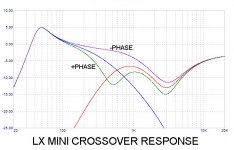
This is what i'm seeking for the summed response curve (green from V - Crossover topology issues):
here
My hint that i did something wrong is that in my response rendering, the summed response is lower than high and low amplitudes at the crossover point. I find it very wrong")
Please help with a knowledge bump.
This is what i'm seeking for the summed response curve (green from V - Crossover topology issues):
here
My hint that i did something wrong is that in my response rendering, the summed response is lower than high and low amplitudes at the crossover point. I find it very wrong
Please help with a knowledge bump.
Last edited by a moderator:
#239
This is what i'm seeking for the summed response curve (green from V - Crossover topology issues):
here
My hint that i did something wrong is that in my response rendering, the summed response is lower than high and low amplitudes at the crossover point. I find it very wrong
Please help with a knowledge bump.
Did you also included, in the summed response, the physical delay between the Low pass and High Pass drivers?
Last edited by a moderator:
Did you also included, in the summed response, the physical delay between the Low pass and High Pass drivers?
No, I did not assume the presence of any drivers. I need to see what the summed output of the filters would be.
(this would be the curve that corrects my actual speaker's output amplified by a ba3)
Last edited by a moderator:
Eh ; that's another hot potato ; i am not seeking a measured acoustic response;
I need the summed filter response curve ; not the speaker's.
You're making this a lot more complicated than it really is.
Your green curve in Post 239 is correct.However, this particular speaker design uses a 2nd-order Linkwitz-Riley alignment, and thus the wiring polarity is reversed on the tweeter driver.
Dave.
Last edited by a moderator:
Did you invert the phase?
Davey said:However, this particular speaker design uses a 2nd-order Linkwitz-Riley alignment, and thus the wiring polarity is reversed on the tweeter driver.
I did not
But after i did invert the HIGH voltage the simulation behaved as expected.I did not expect or know that the high pass filter output should be inverted ; I expected the opposite. I will attempt to learn why.
Thank you very much
Last edited by a moderator:
Hi, thanks to Nelson Pass for this active XO ! I was looking for an analogue active XO for years cause I'm not able to design it. I've only made some loudspeakers with passive crossover.
I would like to play with the Micro Cap sim file when it will be available to download... for now it's giving an error.
As many other here, I would be interested in 3-way single ended version !
cause I'm not able to design it. I've only made some loudspeakers with passive crossover.I would like to play with the Micro Cap sim file when it will be available to download... for now it's giving an error.
As many other here, I would be interested in 3-way single ended version !
Last edited by a moderator:
I tried to save the CIR file but it doesn't work. Some help? error "404 Not Found", thanks
There are plans for a more general crossover.
The LXmini crossover can be stuffed for a variety of loudspeakers. You have the board and existing schematic, and I have posted a MicroCap sim file:
404 Not Found for you to play with.
You can download the Windows demo version of MicroCap from:
Spectrum Software - Micro-Cap 12. Analog simulation, mixed mode simulation, and digital simulation software. SPICE and PSpice(R) compatible circuit simulator. and alter the values to see the resulting curves.
After installing MicroCap demo, you click on the file and it launches you into the screen showing the schematic. On the top bar, click on Analysis, then AC, then Run, and see the result. You can edit the values right on the screen, and after a little practice you can be doing this on
your own. Note that the active elements in this sim are VCVS, voltage controlled voltage sources whose value (gain) is set up as a buffer.

Last edited by a moderator:
To simulate a 1st-order filter, remove the component in the feedback position and replace the first input component with a wire.So, for the sake of knowing, though I already calculated new resistor values for my 2nd. order HP/LP 100 hz crossover, what does one do in the sim schematic with the 2nd. R or C's in the model to simulate a 6db filter... thanks
Dave.
Last edited by a moderator:
Thanks !
Questions regarding the HP eq. section
I removed the upward and downward "humps" by replacing the 18.2k and 15k resistors with 2 - 1k resistors. Is this the right way to do It?
And there is a frequency downward slope towards the 20k response end; it is like -3db down at the end. Is this supposed to be that way also?
And I have not found a method to sum both diagrams....in the program...thanks
- Home
- Amplifiers
- Pass Labs
- LX-mini Crossover Article