Modifying an LXMini crossover for ADS L980 2-way biamplification
Here is how I went about designing and modifying an LX Mini crossover board for my biamplified ADS L980 studio monitor loudspeakers.
The ADS L980 is a 12” 3-way loudspeaker that was manufactured in the mid-1980s. Since it was ADS entry into the studio monitor market, it features high quality, matched drivers in mirror image cabinets. Components consist of a12” sealed box woofer, a 2” high excursion dome midrange and a 0.75” dome tweeter. Crossover points are nominally 450Hz (very low for a 2”) and 5000Hz. Efficiency is 90dB 1W/1M. Passive crossover slopes are 12dB/oct Butterworth. In biamp mode, direct connection is provided to the woofer voice coil but the midrange HPF and LPF and tweeter HPF stay in the circuit.
Listening tests using a miniDSP digital crossover/processor determined that my preferences were for a 500Hz 24dB/oct Linkwitz-Reilly alignment between the woofer and the midrange, leaving the mid-high passive crossover set at the -1.5db position for the tweeter. Since a 24dB/oct L-R filter is two 12dB/oct Butterworth filters cascaded, I decided to design the active crossover with a 12dB/oct Butterworth alignment HPF for the midrange, which would add to the passive crossover Butterworth filter to yield a 24dB/oct L-R alignment, and an active 24dB/oct L-R alignment LPF for the woofer.
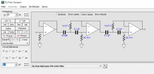
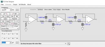
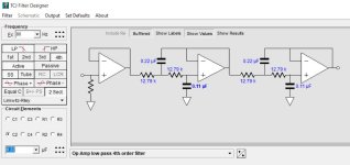
I started with TCJ Filter Designer from Glass-Ware. This program is a bargain at only $10. John Broskie has done the DIY audio community a real service here. Moving away from the optimal component values, which are non-standard, I went with the closest standard cap values first and then the closest 1% resistor values after that. I plugged these into a modified LTSpice version of the LxMini crossover model (link available on one of Papa's sites). This confirmed I was on the right track.
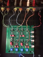
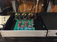
I have posted the schematic mods, the LTSpice plot and file and some photos. Should be pretty self-explanatory. The caps in the resistor spots are a bit twisty as are the resistors in the cap locations. There are a few Jfet current source resistors I stuffed and soldered in by mistake in the L and R section two of the HPF. Ignore them.
How does it sound? The improvement over the miniDSP in detail, imaging and overall clarity is almost shocking, it is so obvious. Well worth the time and investment. Thank you, Papa, for making this wonderful Jfet analog crossover board available through the DIY store and also the matched Jfets and current source resistors.
Here is how I went about designing and modifying an LX Mini crossover board for my biamplified ADS L980 studio monitor loudspeakers.
The ADS L980 is a 12” 3-way loudspeaker that was manufactured in the mid-1980s. Since it was ADS entry into the studio monitor market, it features high quality, matched drivers in mirror image cabinets. Components consist of a12” sealed box woofer, a 2” high excursion dome midrange and a 0.75” dome tweeter. Crossover points are nominally 450Hz (very low for a 2”) and 5000Hz. Efficiency is 90dB 1W/1M. Passive crossover slopes are 12dB/oct Butterworth. In biamp mode, direct connection is provided to the woofer voice coil but the midrange HPF and LPF and tweeter HPF stay in the circuit.
Listening tests using a miniDSP digital crossover/processor determined that my preferences were for a 500Hz 24dB/oct Linkwitz-Reilly alignment between the woofer and the midrange, leaving the mid-high passive crossover set at the -1.5db position for the tweeter. Since a 24dB/oct L-R filter is two 12dB/oct Butterworth filters cascaded, I decided to design the active crossover with a 12dB/oct Butterworth alignment HPF for the midrange, which would add to the passive crossover Butterworth filter to yield a 24dB/oct L-R alignment, and an active 24dB/oct L-R alignment LPF for the woofer.
I started with TCJ Filter Designer from Glass-Ware. This program is a bargain at only $10. John Broskie has done the DIY audio community a real service here. Moving away from the optimal component values, which are non-standard, I went with the closest standard cap values first and then the closest 1% resistor values after that. I plugged these into a modified LTSpice version of the LxMini crossover model (link available on one of Papa's sites). This confirmed I was on the right track.
I have posted the schematic mods, the LTSpice plot and file and some photos. Should be pretty self-explanatory. The caps in the resistor spots are a bit twisty as are the resistors in the cap locations. There are a few Jfet current source resistors I stuffed and soldered in by mistake in the L and R section two of the HPF. Ignore them.
How does it sound? The improvement over the miniDSP in detail, imaging and overall clarity is almost shocking, it is so obvious. Well worth the time and investment. Thank you, Papa, for making this wonderful Jfet analog crossover board available through the DIY store and also the matched Jfets and current source resistors.
Attachments
Last edited:
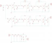
I'm interested in a 24db lr 2 way and have bought two kits. I have made the following schematic and would like opinions if possible. I am crossing over between stereo subs and speakers at around 80 hz. C is 100nf R in the filter is 14k (R4 & R9 would be 28k). The bias resistors specific to the jfets in the kits would be used. I also wanted to buffer the input of the filters. Does this look good?
Attachments
Looks fine. If you bought the store kits, then the input buffers are there already.....

Thanks for the help. Does that mean Q5/Q6 - Q7/Q8 buffers are not necessary? The boards I have from the store don't have input buffers, they go straight to the filter after the pots. My subs have VC so I'm leaving out the pots. I was worried that the filter might be too hard to drive in some cases. I'll be using various preamps. Currently it is a 2sk79 based with a Pimm ccs using mu output and thought an input buffer would avoid any incompatibility.
Last edited by a moderator:
I'm interested in a 24db lr 2 way and have bought two kits. I have made the following schematic and would like opinions if possible. I am crossing over between stereo subs and speakers at around 80 hz. C is 100nf R in the filter is 14k (R4 & R9 would be 28k). The bias resistors specific to the jfets in the kits would be used. I also wanted to buffer the input of the filters. Does this look good?
The HPF values are easy - yours match the filter designer software almost exactly. For the LPF you can see that cap values are non-standard. So, I would change to 0.22 and 0.10 caps and use 12.7K resistors. I found when I modeled my version (500Hz/24LR) in LTSpice, these types of small changes to standard values made virtually no perceivable difference in the resulting slopes and crossover point.
Attachments
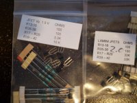
Hi, I have another question about the kits. I have two from the store. The article says the resistors should be around 4k and 10k. One of my sets came with 3.3k and 10k so they fit. The second set came with 33k and 33k and I measured to be sure. The resistors in the pack are 100 ohm and 33kohm. The small label in the bag also lists 100 ohm and 33k for both the other spots. Does this sound right? Are there any downsides to using jfets that require resistors of that value?
Thanks for the help. Does that mean Q5/Q6 - Q7/Q8 buffers are not necessary? The boards I have from the store don't have input buffers, they go straight to the filter after the pots.
The circuit boards I have put out all have buffers after the input pots and
then we drive the filter circuits. This way the impedance of the pot
doesn't interfere with the filter setting.
The buffers are after those pots and also after each filter circuit, the
last buffer driving the output to the amplifier.
vanofmonks
Further thoughts. You can do this with one LXmini board. Section 2 LPF and Section 1 HPF are parts value substitutions. Section 1 of the LPF just requires caps in the resistor positions and resistors in the cap positions.
Section 2 of the HPF is a bit messier. No traces need to be cut but some creative parts placement and jumpers are required. may a bit of air wiring. See attached.
As for input buffers, I would recommend getting the B1 buffer board with matched Jfets from PassDIY.
PassDiy
The schematic shows 18VDC supply but the PDF build guide states voltages from 18 to 24VDC are acceptable. So both boards can run off the same supply. I recommend the 1 amp MeanWell.
https://www.mouser.com/ProductDetail/709-GST25U24-P1J
Attachments
Papa - hate to be a pest but the LXmini board really does not look like any buffers after the pots - or am I missing something?The circuit boards I have put out all have buffers after the input pots and then we drive the filter circuits. This way the impedance of the pot doesn't interfere with the filter setting.
The buffers are after those pots and also after each filter circuit, the last buffer driving the output to the amplifier.
Last edited by a moderator:
What is the screening label on the board?
BIAMP12ERF V1R0 (C)2018 PASSWORKS
You're right. I had forgotten that this board was still around. It was designed around LXmini and assumed amplifiers of equal gain, so it
was not generally thought the level controls would be used. If this is a concern, I have some nice new boards arriving today which
have the additional buffers and some other nice features, but don't feature the EQ for the LXmini.
was not generally thought the level controls would be used. If this is a concern, I have some nice new boards arriving today which
have the additional buffers and some other nice features, but don't feature the EQ for the LXmini.
Last edited by a moderator:
Yeah, I will have to check when I get home to be sure of the label, but I believe both of mine do not have the extra buffer. I know for sure one does not have buffers. It sounds like it would be worth waiting on the new boards as I don't need the eq.You're right. I had forgotten that this board was still around. It wasdesigned around LXmini and assumed amplifiers of equal gain, so it was not generally thought the level controls would be used. If this is a concern, I have some nice new boards arriving today which
have the additional buffers and some other nice features, but don't feature
the EQ for the LXmini.
Last edited by a moderator:
If you don't need the EQ, then the new boards have 6, 12, 18, 24 dB/oct and are
adjustable +/- 1 octave on each pole. They do take up more space.
That sounds great, space is not an issue. When will they be available?
Hi, here is a picture of the two jfet kits I received. One is labeled as vp 1.9v and has what looks to be a reasonable, according to the article, 3.3k for R17-R20 and 10k for R39-R42. The second kit is labeled 2.0 on the bag which I guess is for a vp of 2.0v but the resistors are 33k for both R17-R20 and R39-R42. I measured and confirmed those values. They are way outside the range listed in the article so I'm wondering if they are in fact correct or there was some mistake made. Can someone confirm the correct values for the second kit?
Thanks
Thanks
Attachments
- Home
- Amplifiers
- Pass Labs
- LX-mini Crossover Article