Dear Mr Pass,
I would be very grateful if you can help me answer some questions about jfet buffer (B1) on active crossover.
Firstly, if I had an analog active crossover schematic with opamp as buffer, could I change the opamp for the jfet buffer and keep the original characteristic of crossover? I think the output impedance of jfet buffer is higher than opamp buffer, but don't know if it can make the difference or not.
Secondly, if I used the bipolar power supply (+9V/-9V, for example) and matched JFET, could I omit the blocking capacitor 10uF?
I want to use JFET buffer from 2sk209BL with Yfs = 15mS and Idss = 7 mA
Thanks,
Trung
Last edited by a moderator:
great! I wish you great success!
Thank you for the very kind words Mordikai!!


Cube Audio Magus
Hello Mr. Pass,
I saw in 1 article you use the Cube Audio Magus on open baffle with a LX Mini Crossover. I bought a set of crossover pcb + FET's , the Magus is already in my music room fired by a F2J clone. I like to add a Sub and intend to use the crossover. The Magus is still a bit hot in the sibilants. Did you adress this issue with the crossover (EQ in the upper mids)? If so, I am real interested how to do this, I didn't do any measurements, so I didn't know, where the peak occures (I suppose, somewhere between 5 and 10 k). The second possibility may be to add an R/C combination to smooth down the speakers, but I have no idea witch values to choose.
Greetings from Germany and thanks in advance
Helmut
if I had an analog active crossover schematic with opamp as buffer, could I change the opamp for the jfet buffer and keep the original characteristic of crossover? I think the output impedance of jfet buffer is higher than opamp buffer, but don't know if it can make the difference or not. Secondly, if I used the bipolar power supply (+9V/-9V, for example) and matched JFET, could I omit the blocking capacitor 10uF? I want to use JFET buffer from 2sk209BL with Yfs = 15mS and Idss = 7 mA
Generally speaking you can just replace the op amp with a discrete buffer. The output impedance of the 15mS fet will be about 60 ohms or so, and in my book it is low enough for your purposes. You can parallel Fets for lower if you want. If you want low DC offset, then you will need matching and maybe evena little trimming, depending on what offset you are willing to tolerate.
Last edited by a moderator:
Mr. Pass,
I modified my crossover again since my previous mods did not give me the correct summation of phase response alignment. Here's the final plot for my version of XO at 135 hz. Closed enough to what i needed.
I think the best part of this version is the perfect in-phase response summation with one driver inverted matches closely the phase of LP and roughly flat freq response summation.
Let me know your thoughts on this one.
Thanks Mr. Pass
Regards,
Tom
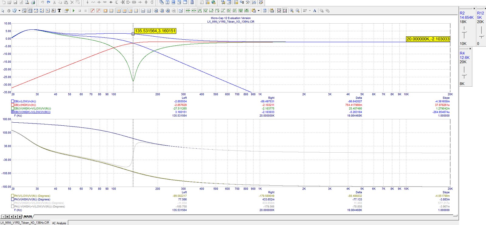
Without duplicating it here, hard to say.
Why don't you let us know after to listen to it?
Thank you for the response, Mr. Pass. I'm putting this ckt together and will report back the sonic result.
Regards,
TD
A very basic question.
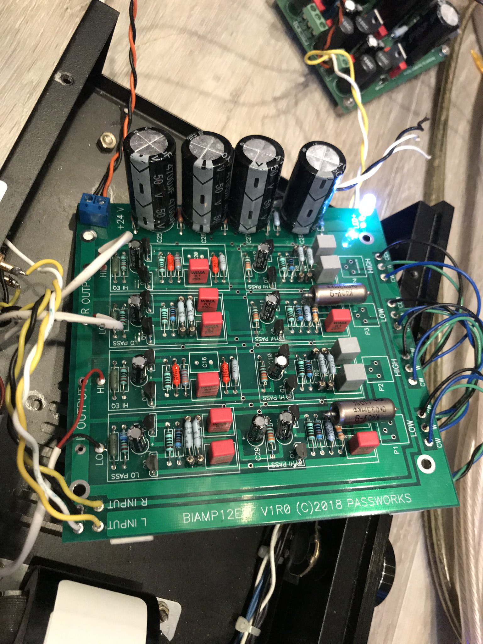
What are the physical dimensions of the board (in mm pls)?? Ive looked everywhere but Ive not been able to find a mention anywhere including the DIYAudioStore or NPs discussion document.
Something to add maybe? TIA
I was tempted to follow the first advice anyone can give "use search". I did, with no success. But i remember when I went trough this thread that the dimensions were specified somewhere as 15cm x 15cm
Last edited by a moderator:
Lucky i saw your posts. Measured from the actual board. Dimension is 5inch x 5inch or 12.5 cm x 12.5 cm ... you're welcome ")
I was tempted to follow the first advice anyone can give "use search". I did, with no success. But i remember when I went trough this thread that the dimensions were specified somewhere as 15cm x 15cm
Last edited by a moderator:
Lucky i saw your posts. Measured from the actual board. Dimension is 5inch x 5inch or 12.5 cm x 12.5 cm ... you're welcome
Many many thanks
I'm playing with early stage layout/chassis options and its pretty damn frustrating wout the correct measurements.
Last edited by a moderator:
Yep.. as I did say.. I've looked everywhere (including a search on this thread) and couldn't find? It's often the simple things that get overlooked. Many thanks anywayI was tempted to follow the first advice anyone can give "use search". I did, with no success. But i remember when I went trough this thread that the dimensions were specified somewhere as 15cm x 15cm
Last edited by a moderator:
Without duplicating it here, hard to say.
Why don't you let us know after to listen to it?
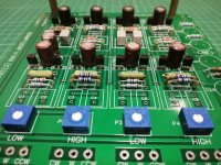
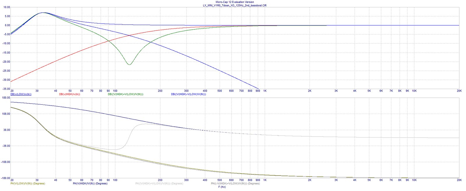
I put together the kit with R,C values of my simulation. Play around with the simulation some more. Did many audition sessions and REW measurement to finally decide that 125 hz XO frequency was the best optimal sonic for my OB speaker.
Man, the sound really comes to life with alot of details and 3D. It trumps over the miniDSP with the same setting at the same XO frequency.
Thank you Mr. Pass for a wonderful gift to the DIY community from a happy DIYer and music listener


With this much of sound quality from this kit, I'm really intrigued and anxiously waiting to get my hands on the new XO ckt with multiple slope settings coming up ahead in the store
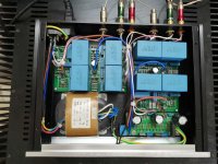
Boy, you have an interesting collection of parts. Its very cool to see you using the K40 caps. What are those red resistors and white resistors?
Thank you sir. I have more goodies hiding under the closet
I really love the sweet and open tones of Russian PIO and Teflon caps. I've been collecting over the years from my past DIY builds and have a full box of them. I'm planning to do another LX mini XO build with all PIO/teflon caps populated and see if there're any differences in sonic result. My guess is It might take a while before I notice any differences since those caps take forever to really break in and sound sweet but it's worth a try anyway.Those Red/green/blue resistors are special 1% precision resistors that I inherited from one of my family member's friend who used to be a WWII electronics engineer. The values of those resistors are very precise to 0.01th. It's amazing how people care about build quality and control many decades ago!
Best,
Tom
to tommydoan84 #494
Hello tommydoan84,
your simulation looks very good to me. 5-6 dB bump at around 35Hz is sometimes good depending on the loudspeaker. All the rest is very flat.
For me there is one simple rule: believe your ears?
Have fun with it!
Greets
Dirk
Hello tommydoan84,
your simulation looks very good to me. 5-6 dB bump at around 35Hz is sometimes good depending on the loudspeaker. All the rest is very flat.
For me there is one simple rule: believe your ears?
Have fun with it!
Greets
Dirk
Last edited by a moderator:
- Home
- Amplifiers
- Pass Labs
- LX-mini Crossover Article