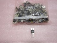
After checking the prices for P-channel FETs on Mouser, I decided to try a bag of 100 Harris RFP6P10 from a USA seller on eBay.
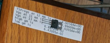
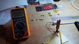
I have access to a Keithley 2600B sourcemeter. I wrote a script that forces current with channel A and measures voltage at the FET with channel B. The current is forced at 11mA, 12mA and 13mA. The three values of Vgs are measured and transconductance is calculated between 11 and 12 mA and then between 12 and 13 mA. The script required about 30 minutes to write and debug. The scripting language is LUA and is no more difficult to learn than BASIC.
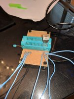
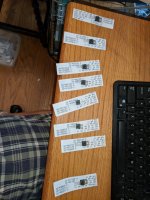
Attached are pictures of the bag of parts, the socket that is connected to the dual channel sourcemeter, and one batch of parts after testing ready to place into individual baggies.
The results are that I have enough matched pairs to let me build some Aleph front ends for amps and preamps.
I have access to a Keithley 2600B sourcemeter. I wrote a script that forces current with channel A and measures voltage at the FET with channel B. The current is forced at 11mA, 12mA and 13mA. The three values of Vgs are measured and transconductance is calculated between 11 and 12 mA and then between 12 and 13 mA. The script required about 30 minutes to write and debug. The scripting language is LUA and is no more difficult to learn than BASIC.
Attached are pictures of the bag of parts, the socket that is connected to the dual channel sourcemeter, and one batch of parts after testing ready to place into individual baggies.
The results are that I have enough matched pairs to let me build some Aleph front ends for amps and preamps.
Attachments
Your point is well taken. If I had no access to the 2600B, a DIY jig would suffice.
Without the 2600B, I personally would use a 236 and 238 that I bought a couple of years ago. The 236 and 238 use an antiquated programming language and have no console level tools. I would have to write a Python program and it would be zero fun writing it. Much simpler to use the 2600B with a Windoze script editor while I have access.
The attraction of the Keihtley SMUs are many. Faster, accurate, repeatable, no fussing with measuring resistors and adjusting power supplies. The results show up in the script debugger console so no writing.
Designing the procedure with the front panel controls showed me that handling a part made it warm enough to mess up the measurement. I ended up using scissors to pick up a part and place it in the socket.
Designing the procedure with the front panel controls showed me that handling a part made it warm enough to mess up the measurement. I ended up using scissors to pick up a part and place it in the socket.
If you measure a larger bunch, changes in room temperature, or someone opening a door, etc. can also bring a drift over the course of measuring a number of devices.
When I did the matching of the Fairchild FQP3P20 I used for the differential pair of my first Aleph build, I first sorted the FETs according to Vgs as "pairing candidates". Final matching of the FETs to make a differential pair was then done as differential matching with the two FETs in close contact as to exclude all temperature drift effects.
")
Best regards,
Claas
Attachments
The idea of connecting matched pairs together "in situ" to measure how good of a match they actually are is an excellent idea. Thank you for sharing your idea and the implementation.
I have read that NP swaps parts in and out of amplifiers to see which ones sound better. That would be your good idea taken to its ultimate conclusion.
Do you measure the pair at one bias current or at multiple currents and calculate gain to see how the pair match for gain?
I have read that NP swaps parts in and out of amplifiers to see which ones sound better. That would be your good idea taken to its ultimate conclusion.
Do you measure the pair at one bias current or at multiple currents and calculate gain to see how the pair match for gain?
I did just the Vgs differential matching at the current at which the FETs were to be used in the frontend of the Aleph Mini / Aleph 30-with-one-output-pair. That is, at around 10 mA / FET.
All FQP3P20s were from the same batch.
No gain matching has been done.
Best regards, Claas
All FQP3P20s were from the same batch.
No gain matching has been done.
Best regards, Claas
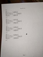
I have automated the measurements of JFETs and power MOSFETs. Here is an example of four consecutive measurements of a JFET. JFET Idss is repeatable roughly 0.1% and gain is repeatable roughly 0.2%. A more rigorous analysis would entail many measurements and some statistics. That would also need temp measurements and possibly temp control. That level of mania is not where I am headed at the moment.
The actual next step is to add a local printer to spit out the paper as the transistors are being tested. At the moment, copying the results, formatting, printing and cutting up the paper takes more time than the actual tests.
The actual next step is to add a local printer to spit out the paper as the transistors are being tested. At the moment, copying the results, formatting, printing and cutting up the paper takes more time than the actual tests.
Attachments
- Status
- This old topic is closed. If you want to reopen this topic, contact a moderator using the "Report Post" button.
- Home
- Amplifiers
- Pass Labs
- Measuring P-channel MOSFETs for Aleph front end