Yes but do i bennefit with having a 10000uF elyt after The CaoMx ?
Most definitely.
You need Caps after the CapMx to be your reserve bank, they are the ones to provide juice in peaks. There's a reason why they are called reservoir capacitors.
I would go 10mF-0.1R-10mF (per rail), space permitting.
... suggestion that it was possible to run the M2x without any daughter board ... ... to remove the daughter board you would just jumper Pin/IO 2 and Pin/IO 4 of the main amp board and leave Pins 3 and 1 unconnected?
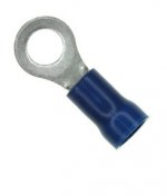
Yes, use a 12 inch piece of uninsulated hookup wire to wrap around bolt #2 several times, then three or four figure-eight loops between bolt #2 and bolt #4, then wrap several times around bolt #4. Use painter's tape or masking tape to secure the wraps in place and to avoid accidental short circuits. Leave bolts #1 and #3 unconnected. You could make yourself a little "wiring harness" with two ring terminals and a piece of insulated wire. Slide these over bolts 2 and 4, secure with star washers and hex nuts, done.
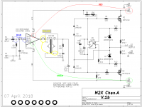
Following the advice of wary skepticism, "trust but verify", you could use your continuity tester / buzzer feature of your digital multimeter to prove to yourself that you have correctly identified the four bolts of the daughter card. Unplug the M2x from the mains (obviously) and wait a couple minutes before doing these tests.
STAGE 1 (BLUE): try all four possibilities and find the leads of R1 and R2 which are connected together; your buzzer will tell you. Now find the daughter card bolt which is connected to that point. Your buzzer will tell you. Voila, that is bolt #2. The job is 25% completed!
STAGE 2 (RED): try all possibilities and find out which daughter card bolt is connected to the 6.35 mm (1/4 inch) blade connector P4, where the positive power supply VPOS attaches. Voila, that is bolt #3. The job is 50% completed!
STAGE 3 (GREEN): try all possibilities and find out which daughter card bolt is connected to blade connector P5, where the negative power supply VNEG attaches. Voila, that is bolt #4. The job is now completed! But we are wary skeptics so we will also perform stage 4.
STAGE 4 (YELLOW): Switch your multimeter to the Ohms setting instead of the Beeper setting. Connect one test lead to either end of R5, it doesn't matter which one, and then see which of the four daughter card bolts has less than 30K resistance to R5. Voila, that is bolt #1. The job is now completed.
_
Attachments
Last edited:
Mark, Thanks for those detailed instructions. I actually figured it out by holding the Ishikawa daughter board up to a light and comparing with the schematic.
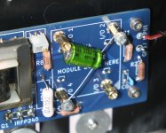
Since I had extra 220uF Nichicon green sleeve capacitors lying around I actually used that as a jumper. I have no idea how necessary it is but most of the daughter boards seem to include that capacitor as the final component. I guess it is supposed to prevent the core of the Edcor transformer from magnetizing? Anyhow, I tried it both ways and since I couldn't hear a difference with the 220uF I left it in.
Feeding the M2x without a daughter board straight from my DAC didn't permit me to achieve my normal listening levels but I built Wayne's BA2018 and that does provide enough juice to run the M2x. I'm still thinking about the sound of the various input options and I expect to write a post about that soon.
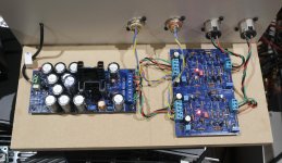
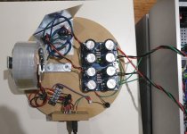
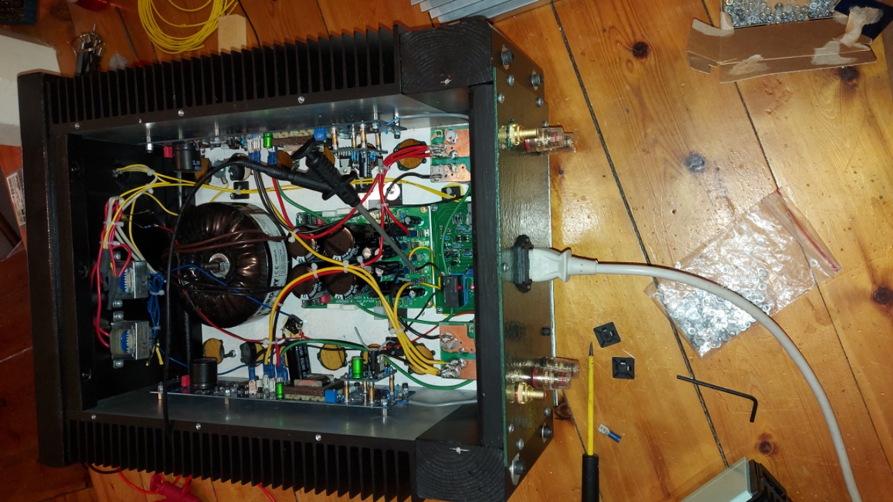
Finally, I had been having persistent problems with a humming noise which I wasn't able to eliminate so I decided to build an external power supply to use with the M2x and perhaps future projects. In the best DIY tradition I used the materials I had lying around to mount the PSU as you can see in the picture. The good news is the M2x is now dead quiet. The bad news is I have no idea if the improvement is because of the distance between the PSU and the Edcor Transformers or the new Antek transformer and PSU board I built.
Since I had extra 220uF Nichicon green sleeve capacitors lying around I actually used that as a jumper. I have no idea how necessary it is but most of the daughter boards seem to include that capacitor as the final component. I guess it is supposed to prevent the core of the Edcor transformer from magnetizing? Anyhow, I tried it both ways and since I couldn't hear a difference with the 220uF I left it in.
Feeding the M2x without a daughter board straight from my DAC didn't permit me to achieve my normal listening levels but I built Wayne's BA2018 and that does provide enough juice to run the M2x. I'm still thinking about the sound of the various input options and I expect to write a post about that soon.
Finally, I had been having persistent problems with a humming noise which I wasn't able to eliminate so I decided to build an external power supply to use with the M2x and perhaps future projects. In the best DIY tradition I used the materials I had lying around to mount the PSU as you can see in the picture. The good news is the M2x is now dead quiet. The bad news is I have no idea if the improvement is because of the distance between the PSU and the Edcor Transformers or the new Antek transformer and PSU board I built.
Attachments
Friends, a quick question: is the 4N35-X000 a suitable swap for the standard 4N35?
https://nz.mouser.com/ProductDetail/Vishay-Semiconductors/4N35?qs=sGAEpiMZZMsDgH01pahWBsDBAFuUQFOv
4N35-X000 Vishay Semiconductors | Mouser New Zealand
The X series appears to be fundamentally the same, but with higher forward & surge current ratings, plus higher output power dissipation.
The regular versions are currently out of stock at Mouser & Digikey.
Post nr3
"WARNING: BLASPHEMOUS HERESY! DO NOT READ THIS! Some DIY builders of the M2 amplifier, using the very fine “Tea‐Bag” circuit board, have reported a problem to the diyAudio forums. Their M2 amplifier’s output offset voltage is negative, and no setting of trimmer resistor RV1 removes this negative offset. I would like to gently mention a possible fix: leave R7=47K, but change R6 to 37K and change RV1 to 20K. Now (R6+RV1) can vary from 37K to 57K, in other words, from (10K less than R7) to (10K more than R7). This lets you null out either polarity of offset voltage. However, to faithfully reproduce Nelson Pass’s original M2 design, the M2X schematic and PCB silkscreen do not include this modification. M2X has R6=47K and RV1=5K. If you decide to make this R6,RV1 modification on your M2X, don’t tell anyone. And don’t quote me."
"WARNING: BLASPHEMOUS HERESY! DO NOT READ THIS! Some DIY builders of the M2 amplifier, using the very fine “Tea‐Bag” circuit board, have reported a problem to the diyAudio forums. Their M2 amplifier’s output offset voltage is negative, and no setting of trimmer resistor RV1 removes this negative offset. I would like to gently mention a possible fix: leave R7=47K, but change R6 to 37K and change RV1 to 20K. Now (R6+RV1) can vary from 37K to 57K, in other words, from (10K less than R7) to (10K more than R7). This lets you null out either polarity of offset voltage. However, to faithfully reproduce Nelson Pass’s original M2 design, the M2X schematic and PCB silkscreen do not include this modification. M2X has R6=47K and RV1=5K. If you decide to make this R6,RV1 modification on your M2X, don’t tell anyone. And don’t quote me."
Post nr3
"WARNING: BLASPHEMOUS HERESY! DO NOT READ THIS! Some DIY builders of the M2 amplifier, using the very fine “Tea‐Bag” circuit board, have reported a problem to the diyAudio forums. Their M2 amplifier’s output offset voltage is negative, and no setting of trimmer resistor RV1 removes this negative offset. I would like to gently mention a possible fix: leave R7=47K, but change R6 to 37K and change RV1 to 20K. Now (R6+RV1) can vary from 37K to 57K, in other words, from (10K less than R7) to (10K more than R7). This lets you null out either polarity of offset voltage. However, to faithfully reproduce Nelson Pass’s original M2 design, the M2X schematic and PCB silkscreen do not include this modification. M2X has R6=47K and RV1=5K. If you decide to make this R6,RV1 modification on your M2X, don’t tell anyone. And don’t quote me."
This worked perfectly for me with the same issue.
")
Am just getting started on the M2X which I will build with the MountainView Class A daughter board and an external linear PSU. Have been able to get the PCBs and order all of the components except for these two that I cannot find anywhere -- and am hampered by being a beginner who doesn't know all of the alternate options:
1. P3-P8: the Male Faston 1/4" Blades (12) and
2. C2: the 10uf, 50v, NP capacitor (2)
Will apologize for not having read all 527 pages of this extraordinary thread and if the answer is in a post above, let me know.
1. P3-P8: the Male Faston 1/4" Blades (12) and
2. C2: the 10uf, 50v, NP capacitor (2)
Will apologize for not having read all 527 pages of this extraordinary thread and if the answer is in a post above, let me know.
Last edited:
1. There are a number of options. I happen to like Digikey's "View Similar" functionality better than Mouser's, but YMMV. This is the Mfr part number for a suitable replacement.
Keystone Electronics - 1287
If you like the ones that have the extra little "stability tabs" on the bottom similar to the original part. This is a good one.
TE Connectivity - 1217421-1
I like the cut strip of 100 pieces b/c I use a ton (sorry Zen Mod). However, for just a few, buying them in smaller quantities already cut and separated works wonderfully too.
2. Digikey has some of the the preferred Nichicon NP "Green" in stock. I'd go with that. If Mouser is your preferred source, you'll be waiting a bit. Others may know an equivalent sub, but I believe I read that Nelson Pass really liked that specific part.
Keystone Electronics - 1287
If you like the ones that have the extra little "stability tabs" on the bottom similar to the original part. This is a good one.
TE Connectivity - 1217421-1
I like the cut strip of 100 pieces b/c I use a ton (sorry Zen Mod
). However, for just a few, buying them in smaller quantities already cut and separated works wonderfully too.2. Digikey has some of the the preferred Nichicon NP "Green" in stock. I'd go with that. If Mouser is your preferred source, you'll be waiting a bit. Others may know an equivalent sub, but I believe I read that Nelson Pass really liked that specific part.
IAIMH: Got the connectors from DigiKey as 1217421-1 but cannot find the caps for the life of me. Tried all of the Capacitor tables in DigiKey but apparently don't know what to look for. Where are the "Green" items at? What type caps are these (e.g., "Aluminum Electrolytic").
Thanks as always.
Thanks as always.
IAIMH: Thanks, do have the BoM but for some reason couldn't find it. Your link worked and now I've got all the components coming. Now for the next step: linear PSU. Been reading the threads here and they are very helpful. Also found this source which is good for beginners:
Building a Gainclone chip amp power supply.
The folks on this site are the best -- thanks for the real help.
Building a Gainclone chip amp power supply.
The folks on this site are the best -- thanks for the real help.
IAIMH: Thanks, do have the BoM but for some reason couldn't find it. Your link worked and now I've got all the components coming. Now for the next step: linear PSU. Been reading the threads here and they are very helpful. Also found this source which is good for beginners:
Building a Gainclone chip amp power supply.
The folks on this site are the best -- thanks for the real help.
If I were you I would just build the Universal Power Supply from the DIYaudioStore.com using an Antek transformer except I just checked and the only on in stock is the 500VA version which is overkill but I believe would still work fine. AN-5218 - 500VA 18V Transformer - AnTek Products Corp If you decide to go that route PM me and I'll send you my Digikey parts list.
Also, I want to suggest you build a different daughter card than the Mountain View which was my least favorite of all the ones I tried. The Tucson is a great sounding a card and the LT1122 is a good opamp with it. Of course, everybody has different preferences when it comes to the input stage so that is just my opinion. Norwood sounds amazing but those SMD components are a bit tricky.
MJ: Time machine would be useful now. Am always interested in something new so will plug through the linear PSU learning process.
PaulInWA: Thanks for the suggestions and link. Will order that transformer today. Already have the BoM for the Universal Power Supply and have ordered the pcbs from DIY. Always like to have something in the mail and, now, if only our Italian chassis friends would get back from vacation, we can get things assembled.
Your comments about MountainView are interesting and helpful. My nascent understanding of Class A is that it amplifies the signal literally with no alterations. the M2X is listed as a push-pull device and, so, I do not know how Class A can happen with a push-pull design -- that, as far as I know, always divides the signal into + and - segments and, so, has a crossover point. With Emotiva amps, they use something called high-bias Class A that simply keeps both rows of transistors "live" for the first 60 watts. But the crossover is still there. Think the advantages of the ACA that I am hearing is that there is no crossover distortion.
But the pundits on this site can clear up my confusions.
Couple of questions for the forum:
1) I am finding that I am not needing to adjust DC Offset when switching between the Ishikawa and Cedarburg. Do you guys check DC offset each time you switch cards?
2) When using the Ishikawa board, there is no turn on "thump" when I power up the amp, it doesn't make any sound. On both the Cedarburg and the Tuscon cards I get a noticeable "thump" through the speakers at turn on. These are the only cards I have tried so far. Any ideas and is this normal?
Thanks for your input. Kurt
Craigl59 - Interesting that the BOM doesn't list wattage but all the other DIY First Watt builds I have done use 1/4 watt Vishay/Dale resistors like this one https://www.mouser.com/ProductDetai...zyu1Hy8B0Bg==&countrycode=US¤cycode=USD
I believe there are some people that would argue for using more exotic resistors but I don't recall any posts comparing the sonic quality of those builds.
As for your question about Class A push-pull etc. etc.. I have no idea. I don't claim to understand the circuit design, I just build, and listen to the First Watt amps. To my ears the M2x is the best of the First Watt amps that I have built and the ability to swap out daughter boards is a terrific and fun feature. Different daughter cards do sound slightly different so that is an education in listening all by itself. The only gotcha I encountered with the M2x was some background noise from the power supply which I solved by moving it outside of the chassis. I think most builders don't run into that problem.
- Home
- Amplifiers
- Pass Labs
- The diyAudio First Watt M2x