Follow-up on the CPU heatsink temperatures: emboldened by Mark pointing out that nothing terrible is going to happen, I tried running the CPU sinks without any fan.
Temperature is measured on top of one of the two MOSFET (only one channel at this point). Turns out, if you're willing to run at ~80 degC (at a room temperature of 71F), this works fine. However, inside an enclosure your milage will vary...
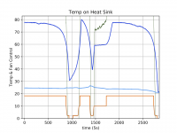
The dark blue curve in the graph shows what happens (ignore the other curves):
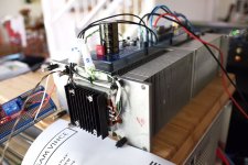
The plot updates on the left, so time runs from right to left. I started the run with the sink lying on the side (picture), and the temperature stabilized around 78 degC.
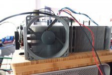
I then put a fan (picture) such that it just blew through the fins of the sink, not giving any air movements to the MOSFET assembly directly, and the temperature dropped to a bit below 60 degC (it would go much below that if I were to fan the top, too, even at very low RPM).
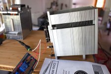
I thought by turning the cooler so that air could rise through the fins I would produce some chimney effect (picture) and the cooling would work better, but in this configuration the temperature went quickly above 80 degC, so I aborted.
The leftmost part of the curve is then going back to the first configuration on the side, no fan, and the temperature got stable again around 78 degC.
Temperature is measured on top of one of the two MOSFET (only one channel at this point). Turns out, if you're willing to run at ~80 degC (at a room temperature of 71F), this works fine. However, inside an enclosure your milage will vary...
The dark blue curve in the graph shows what happens (ignore the other curves):
The plot updates on the left, so time runs from right to left. I started the run with the sink lying on the side (picture), and the temperature stabilized around 78 degC.
I then put a fan (picture) such that it just blew through the fins of the sink, not giving any air movements to the MOSFET assembly directly, and the temperature dropped to a bit below 60 degC (it would go much below that if I were to fan the top, too, even at very low RPM).
I thought by turning the cooler so that air could rise through the fins I would produce some chimney effect (picture) and the cooling would work better, but in this configuration the temperature went quickly above 80 degC, so I aborted.
The leftmost part of the curve is then going back to the first configuration on the side, no fan, and the temperature got stable again around 78 degC.
Attachments
G5 heatsink
LATB:
That's a very interesting set of results.
I don't know the intended orientation of these heatsinks in the G5. Were these oriented in the mac pro chassis like you show your first picture? For some reason, I thought these were mounted with the long dimension along the vertical. But I have no particular reason to say that, other than that is how these strike me.
I picked up a few of these on Ebay to mess around with. I may end up using a fan, but I'd rather not, so we will see.
BTW, lots of interesting fan controllers for PC-oriented uses on eBay that are cheap and also provide displays of temperature, etc. 12v and you are running.
One last question: your measurements were for your original setup with 2 MOSFETs mounted to the single heatsink, right?
LATB:
I don't know the intended orientation of these heatsinks in the G5. Were these oriented in the mac pro chassis like you show your first picture? For some reason, I thought these were mounted with the long dimension along the vertical. But I have no particular reason to say that, other than that is how these strike me.
see e.g. here.
The measurements were with both MOSFETs on one of the two sinks.
G5 heatsink
Hmmm.
I found a shot of the interior of a G5, and they do indeed have these sinks on their sides, like you show in your first photo.
After a quick thought, I can easily see why you saw a quick temperature rise when you tipped yours up a bit, trying to exploit the possibility of a 'chimney effect', but this slowed convection currents down, and also was moving warmer air further up the stack, instead of up and off the fins, as the first photo would suggest.
In any case, to a first approximation, if we put *one* MOSFET per sink, given your data, we can expect a delta T half that of what you measured, all other things begin equal. This suggests a steady state of approximately 51C, or around 124F in the vicinity of your measurement location. That seems quite tolerable. I would expect temperatures on the perimeter of the heatsink base, where fingers might touch, to be quite a bit less.
But in any case, these results show that these heatsinks can likely be used in a passive cooling manner, exposed externally to any case holding the boards themselves. As you say, if you put these in an enclosure, you must ventilate really well ('cheese grater' amp) and/or add fan(s). The use of fans clearly liberate you to mount these in just about any orientation you choose.
Nice work! Thanks for sharing about this project- This approach can radically reduce the cost of building these amps, now, because the heat sink cost has come substantially down, and it appears one is not necessarily forced into active cooling, but rather can do this by design choice.
I know what I am going to be doing when those G5 A1047 heatsinks arrive!
This is very interesting, LATB. Please share the schematics and software. I like using MCU's and if you've sorted out the PID's, even better.
I put it up on gitlab.comLATBauerdick / fc * GitLab.
This is not "production code", but mostly to try out things. I don't think a MCU is really needed here, Mark's regulator will do just fine -- but this is handy if you want to log temperatures and play around.
I didn't put much effort into documenting things, just ask if something is unclear.
Tape and grease? Looks like it...
I put it up on gitlab.comLATBauerdick / fc * GitLab.
This is not "production code", but mostly to try out things. I don't think a MCU is really needed here, Mark's regulator will do just fine -- but this is handy if you want to log temperatures and play around.
I didn't put much effort into documenting things, just ask if something is unclear.
Downloaded, thanks LATB. I'm not going to use it right away, but archived it for when I need it later.
There are also other advantages of using a MCU. Temperature display, auto-shutdown in the event of the temperature exceeding a preset value, like when a fan stalls or doesn't work optimally, etc.
I love this amp so much I want one for the Lab and one for the dedicated room. Started the order process for a mono version. The last one was dual mono, but this will be a true mono and I'm going to build all the boards find the two I like best and keep those in each amp. I already have the Ish, so just have what 4 more? 
Here we go again!
JT
Here we go again!
JT
Its a great amp. I'm running Mountain View, and its great. I have the Ishikawa boards completed, but I'm not going to use it till I set up a distortion measure rig.
Our Covid shutdown has completed, and the beach season has arrived to take me out of the house on weekends, so I am behind on building the other boards.
@pfarrell has kindly offered to do my SMT work, and the Norwood boards are due in one day soon. The last two: Tuscon - only needs the DIP socket soldered on, and the Austin - all parts are in, I will be doing solder work next weekend, and have all the boards completed.
Then, I just need listening time. Not sure how long its going to take to get the tops on those amps at this point. Perhaps one of the board sets will crystallize as "the one" early on. Not sure I will count on that at this point.

please explain since I only know about my own BOMs. How do they get there? Does the store put them there?
I posted some Mouser M2x links 10 months ago. See post 2369 in this forum.
https://www.diyaudio.com/forums/pass-labs/321925-diyaudio-watt-m2x-237.html#post5854189
I do a "Project" for my Mouser BOM and then if I want to share it there is a button to do that which generates a link which can be copied and pasted.
No doubt some of my BOM parts are either out of stock or no longer stocked. This is especially true of Vishay Dale RN55-series resistors. Quite often alt packaging (reel vs. bulk) or slight differences in value (105 ohms vs 100 ohms) can make a big difference in cost.
With capacitors especially, always check diameter or size and lead spacing against the original part. Reel packaged parts can have different lead spacings than bulk if they kink out (widen) the lead spacing for reel (tape) feed parts. Some transistors come both ways as well. So it's not just values and voltages.
Disclaimer: although my BOMs are as accurate as I can make them, and corrected after my build if I missed something, I highly recommend you check them against the schematic and/or original parts list.
Ahhh, thanks. I use those all the time but sometimes there are a lot of part numbers to enter which is a pain. I looked through Mouser and couldn't find them is why I asked. I personally haven't tried various file copy options. I have taken advantage of Tea Bag's kit capabilities recently for stuff that he does. Allows me to redirect my time to the actual build. Kind of like ordering a kit from the store.
Thanks for explaining it to me.
How do you like your SL-1200G. After I have a working system or two, that is my next project. After the speaker project.
Glad you're out and about.
Don
Thanks for explaining it to me.
How do you like your SL-1200G. After I have a working system or two, that is my next project. After the speaker project.
Glad you're out and about.
Don
One more thing. Many of my Mouser BOMs use Vishay/Dale RN55-series resistors for the 1/4 watt sizes. These are considered by some to be "the best" of the commonly available parts. Pass Labs projects (Papa and Wayne) tend to specify Vishay/BC Components SFR-series. Lately I have been looking to use Vishay/Beyschlag MBA-series as they seem more readily available than the Vishay/Dale RN and spec as quieter than the Vishay/BC Components SFR resistors.
- Home
- Amplifiers
- Pass Labs
- The diyAudio First Watt M2x