Yes, I know green Nichicon is mentioned in schematic and ordered some of these…..then I noticed the FG type and got curious.
Ok so NPO (COG) is a ceramic type with zero temp drift for C0. Think I have some of those…..a stacked foil type. They are very small and compact. I may have Mica types also. Will see how it fits with distance between terminals.
The white/gray multiturn that is used …...is that one of the expensive low temp drift gray Bourns type? …..I think 50 ppm/K instead of 100 ppm/K for blue "normal" types?
This type should be good as C0 I hope:
C315C221J5G5TA | KEMET Goldmax 300 Series Keramisk kondensator med flere lag (MLCC), 220pF, +-5%, 50V dc, Dielectrikum: C0G, Hulmontering | RS Components
…..a multilayer type.
C315C221J5G5TA | KEMET Goldmax 300 Series Keramisk kondensator med flere lag (MLCC), 220pF, +-5%, 50V dc, Dielectrikum: C0G, Hulmontering | RS Components
…..a multilayer type.
Sounds like the optocoupler died too. Did you also measure the voltages at the source resistors? Are they ok?
Thanks, what is the dc offset range?
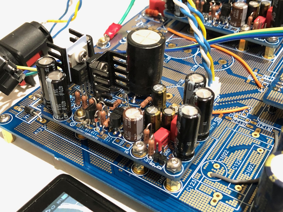
For those of you who are building the Melbourne daughter board, I have verified that it works and plays music as a headphone amp using the Yarra motherboard to provide power and I/O connections. I have not had time to connect to an actual M2X, since mine is sort of torn-apart and now missing a PSU. It should work just fine though. I am driving 55ohm headphones with it so a 600ohm Edcor should be no problem.
Last edited:

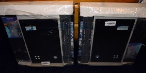
For my M2X build I received 2x 5u deluxe chassis from HiFi2000 shop. I built as mono blocks to have space for a large PSU with good distance from transformer to M2X boards (part of avoiding Edcor hum pickup issues other has faced). Apart from that I like mono blocks. I ordered two sets of connector kits from DiyAudio Store and as you can see from the picture I have back panel "mono block cut outs" for the connectors. I like two sets of speaker terminals as this makes it easier to use two sets of speaker cables for bi-wire. These chassis are heavy!
If other want same mono block panels I assume 30 Euros can be saved as this is the price to make the "cut file".
So far so good…….I have many projects in the pipeline...….")
If other want same mono block panels I assume 30 Euros can be saved as this is the price to make the "cut file".
So far so good…….I have many projects in the pipeline...….
Attachments
I am starting to assemble an M2x to compare with my advanced ACA amplifiers. I finally decided to start with an Antek AS-4218 (400VA, 18V + 18V), including the steel case made to enclose the transformer. I'm leaving an option open for a pair of 200VA transformers if necessary. I found a 400mm deep 2.5U chassis with a back panel that was already machined for IEC inlet and all signal & speaker connectors.
I was looking at a trial fit of the M2 main boards with the Melbourne daughtercards and found that they will just fit, as long as the main boards are positioned carefully on the heatsinks. There would have been more room in a 3U chassis, not to mention a 4U or 5U. I'm trying to keep the Edcor signal transformers as far away from the big power transformer as possible, so it's likely that I would have needed a custom mounting hole pattern regardless of which chassis I used.
I was looking at a trial fit of the M2 main boards with the Melbourne daughtercards and found that they will just fit, as long as the main boards are positioned carefully on the heatsinks. There would have been more room in a 3U chassis, not to mention a 4U or 5U. I'm trying to keep the Edcor signal transformers as far away from the big power transformer as possible, so it's likely that I would have needed a custom mounting hole pattern regardless of which chassis I used.
Last edited:
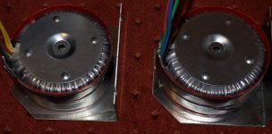
I decided for 500 VA transformers. One for each chassis. Then I hope the flux will stay inside the core. It is standard Talema Czech made. I found a good offer. Think they are ok. A lot of good stuff are Czech made! ….then I applied magnetic shielding. Also the steel rondel is speciel grained steel for magnetic shielding (poor mans mu-metal). I got the shielding from Don-Audio.
Attachments
I built an M2x in a "Chineseum" chassis purchased from eBay, one of the ones you find when searching for Class A Audio Chassis. There were no holes drilled in the heatsinks, no holes or "cut outs" in the back panel, no holes in the front panel. Just a metal box including enormous heatsinks.
It turned out to be humanly possible to get all of the holes drilled in exactly the right places, on the first try. Even the holes that are drilled and M3-tapped on the heatsinks. I laid out the hole pattern on a piece of paper, carefully taped the paper to the heatsink, and then used a Center Punch to make a dimple exactly where each hole center should go. This guided the drill bit quite well and I had no difficulty fitting all seven bolts that attach the channel amp PCB to the heatsink. No misalignment, no re-drilling.
Rear panel was easier since it has no heatsink fins that need to be protected. To get the rectangular cutout I drilled lots of round holes "inside the line", knocked out the center piece, and then cleaned it up with a 1" wide flat file. Front panel was easiest of all: just a single 3mm round hole for an LED.
The big Eureka! for me was: DO NOT put masking tape on the workpiece and then draw guidelines and crosshairs on the tape. That tape shifts and the markings smear. Instead, lay it all out on a clean sheet of paper, tape the paper down to the workpiece securely, and use a center punch to "communicate" the location of the hole-centers, into the workpiece.
Ok....can see there are many "China chassis"......like this one:
New aluminum Class A chassis / power amplifier chassis/home DIY audio chassis | eBay
The M2X I built is not what you can call cheap in absolute terms. But maybe relative to what corresponding factory mono block amps would cost.
To buy pre-drilled Deluxe chassis saves time but cost "a bit" more.
New aluminum Class A chassis / power amplifier chassis/home DIY audio chassis | eBay
The M2X I built is not what you can call cheap in absolute terms. But maybe relative to what corresponding factory mono block amps would cost.
To buy pre-drilled Deluxe chassis saves time but cost "a bit" more.
respond to MEPER and Mark Johnson
Metalworks on an amplifier are often time consuming and sometimes a
hard test for your nerves at patience!
But you know: if it is playing the first music you will forget about the pain.
to MEPER: I am very curious about your cases. I am sure they will become
fantastic!
Transformers also look very good and more than big enough. I can imagine
big banks of caps.....
Greets
Dirk
- Home
- Amplifiers
- Pass Labs
- The diyAudio First Watt M2x