... Melbourne ... that comes from a single ended Class A front end ...
I think you need to adjust your marketing spiel. Your front end is a PNP differential amplifier, it's not single ended in the least. A single ended circuit is neither differential nor push-pull. Your front end does not meet the criteria.
However. Your second stage is indeed single ended Class A. Just like the second stage in every IC opamp including the uA741 from 1969. Just like the second stage in all of the beginner's power amps in Bob Cordell's book and Douglas Self's book and Ben Duncan's book and Randy Slone's book. (Before they begin to discuss push-pull second stages). But the second stage is not the front end and none of these amplifiers have a "single ended Class A front end".
_
Attachments
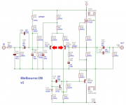
The front end of M2x is whatever input circuit is included on the daughterboard you bolt in. So if you bolt in an Austin daughterboard, for example, then your M2x has got a push-pull Class A diamond buffer front end. If you plug in a Norwood daughterboard then your M2x has got a differential-JFET front end. And if you plug in a Melbourne daughter board then your M2x has got a differential-bipolar front end.
The only way to make your M2x amplifier have a single ended Class A front end, is to un-bolt the Melbourne daughter card and replace it with a different card whose input stage is indeed single ended Class A. If you do this then, yes indeed, a non-Melbourne M2x does exist whose front end is single ended Class A. But it misleads the reader to mention single ended Class A when discussing Melbourne itself.
"There is also an incredible smoothness that comes from a single ended Class A front end" -- on another card not named Melbourne.
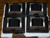
Clarifying question here before I click purchase: The edcore part in BOM for M2X shows PC600-15K. The edcore site shows both 600 ohm to 15k ohm (1:5) and 15k ohm to 600 ohm (5:1). I assume that because the BOM has the 600 first I want 600 ohm to 15k ohm (1:5). But we all know Mr. Assumption...
I think you had better read the
Official M2 schematic
thread here on diyAudio. It was started in 2015 by Nelson Pass, and to date it has accumulated more than 3170 posts. If there are pitfalls or difficulties or secret tricks to use when buying the Edcor transformer that Nelson Pass chose for the M2, that thread would be the first place, and the best place, to look.
Very closely study what went wrong when diyAudio member kbergsson tried to order Edcor transformers for shipment to Norway. Once you discover what he did wrong .... don't do that!
And continue with the remainder of anecdotes and tales of success / tales of woe, which fellow diyAudio members have posted. It would be a terrible shame to ignore their hard-won knowledge.
Clarifying question here before I click purchase: The edcore part in BOM for M2X shows PC600-15K. The edcore site shows both 600 ohm to 15k ohm (1:5) and 15k ohm to 600 ohm (5:1). I assume that because the BOM has the 600 first I want 600 ohm to 15k ohm (1:5). But we all know Mr. Assumption...
Hi Sesquipedalio, The edcor transformer you’ll need for each amp board is the PC Series Transformer, Impedance: 600 Ω to 15K Ω (1:5 ratio).
Finally, I managed to locate locally (South Africa), the only "do not substitute" item; the MV5075C red LED for the Mountain View daughter boards.
If any prospective M2x builders in South Africa read this and want some, just drop me a PM and I'll put you in contact with the supplier.
If any prospective M2x builders in South Africa read this and want some, just drop me a PM and I'll put you in contact with the supplier.

Why would you quote that entire posting?
Just point to the post number or take a snippet of the post. Just a waste of space.
+1
 OT rude posts removed.
Hello
now powered up the M2 ishikawa for offset and problem adjustment.
test conditions:
*RCA plug in short circuit.
*16 ohms load resistance on speaker outputs
*on the 230v is tested with a 60w bulb in series.
Observation at power-up:
*Only the card powered, the 60w bulb lights up for 5s and then goes out.
*with the motherboard equipped with ishikawa connected to the PSU board the lamp remains off and then lights up gradually.
*same symptom for channel A and channel B
So I suspect a short circuit
That is my problem.
when do you think?
Did I understand correctly the fact of short-circuiting the RCA input socket?
Thank
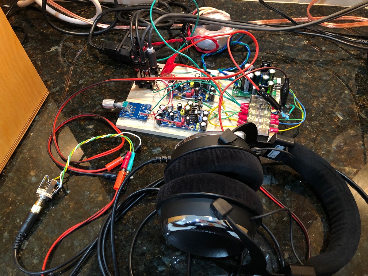
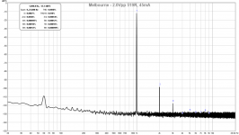
Some measurements of the Melbourne:
The Melbourne Class A Headphone Amp and Pre-amp
I was shocked how good it sounded driving my headphones. Both 250R and 50R - sounded clean and powerful. No audible hum. This is with +/15.5v rails provided by Mark Johnson design and Prasi layout BJT cap Mx and linear 15v trafo.
2Vpp into 240R load:

This was as close as I could get to providing a 600ohm load to emulate the Edcor (519R). 2Vpp into 519R:

4Vpp into 519R:
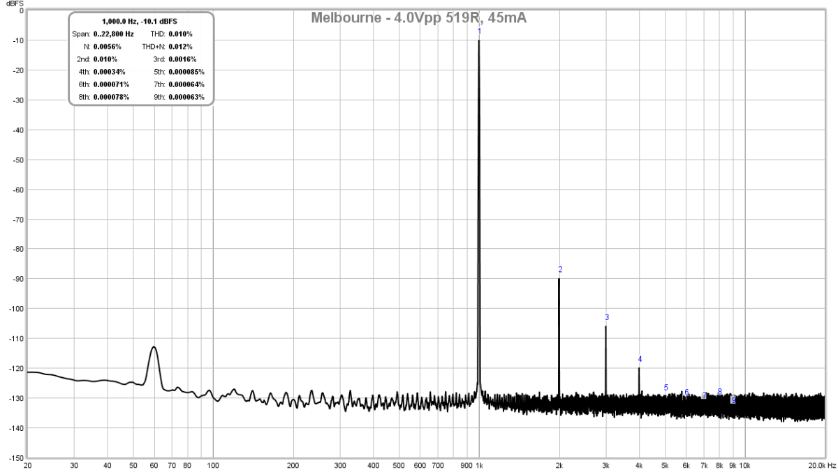
I think this is a very nice harmonic distortion profile and should be a good input stage for the M2X.
The Melbourne Class A Headphone Amp and Pre-amp
I was shocked how good it sounded driving my headphones. Both 250R and 50R - sounded clean and powerful. No audible hum. This is with +/15.5v rails provided by Mark Johnson design and Prasi layout BJT cap Mx and linear 15v trafo.
2Vpp into 240R load:
This was as close as I could get to providing a 600ohm load to emulate the Edcor (519R). 2Vpp into 519R:
4Vpp into 519R:
I think this is a very nice harmonic distortion profile and should be a good input stage for the M2X.
Attachments

Last edited:
I am coming to the end of my tether....
rebuilt the right channel again and tested it on the bench for some time - came up to normal bias point, adjusted the offset easily and stable for about 2 hours before I turned it off.
Tested it in my test system - came right up, offset started at 140mV in both channels, settled to around 1mV fairly quickly. Bias good and overall seemed to be behaving, no hum or hiss at all from speakers. ( I did build little mumetal enclosures for the edcors.
absoutely lovely music playing and kept watching it carefully for the first 90 min - no change in behavior at all with heatsinks settling down at 52deg C and the little tabs on the fets sitting about 10 deg higher.
Left it playing for about 3 hours, checking on it every 30 min odd. Final check - same channel dead
odd thing is that the 3A fast blow fuse does not go, just the negative rail of the SMPS current limiting as it is shorted to ground through the 2SJ201
This will be the third set of these precious mosfets to have been sacrificed without me understanding the circumstance of the failure.
- given the general start up and initial stabilization, the amp is working
something catastrophic is happening after some time and I have no means to measure it
perhaps sticking a gopro on the multimeters and seeing what happens when it does this again - assuming I can find anymore fets
..dB
It would be comparatively inexpensive to perform the experiment of temporarily replacing the rare Toshiba FETs with ordinary IRFP240/IRFP9240 industrial FETs, and seeing whether or not those blow out too. You could also connect some 5000W unidirectional TVS diodes across the rails, or across each rail individually, just to deal with random spikes and ick noise put out by the SMPSs. (possibility??)
Last edited:
{headhung in shame} {tail between legs} - if only we had the appropriate emoji's to appropriately express my embarrassment and shame
KERATHERM!!
I know ZM in particular preaches this loudest of all - the store was out of stock and I ordered what I thought would be a suitable alternative option from wakefield.
I kept studying the schematic trying to figure out how the drain might short to ground without the mosfet actually shorting out between its pins. I thought I would try an experiment and remove the daughter board - not that I thought that was to blame but just wanting to remove all variables. them I inserted a thin plastic sleeve between the fet and the heatsink after unbolting it - no more short !!
this would explain why I managed to fix everything with replacing the fets as I was replacing the heatpad too - these must not be up to snuff and although I am not seeing visible holes in the pads, they are shorting the output devices to the heatsink and thus ground.
If only I had not run out of keratherm before starting this project/or ordering more when i did and before they ran out of stock - will soon have more on the way.
thanks all for thinking about this and feel free to laugh along as i beat my head while chanting and walking in a circle.
..dB
- Home
- Amplifiers
- Pass Labs
- The diyAudio First Watt M2x