If it doesn't have a transformer, can you still call it an 'M'2?
Maybe MX2 then.
But the song remains the same.
 OPAL? Optical Pass AKSA Lender
I suggest you call it a high current WHAMMY. An amplifier with so much active gain that negative feedback is required to tame and control it, and with a complementary MOSFET source follower output stage, and with Pass Labs' 4N35 optoisolator bias scheme for Class A operation. However your output stage bias current is increased by a factor of (10/0.47) = 21 times compared to the WHAMMY.
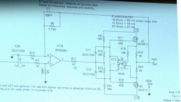
WHAMMY schematic (from Wayne Colburn's 2017 talk at Burning Amp) below. His front end gain stage was made from an IC rather than discretes. Most importantly, Wayne, like you, did not include an Edcor transformer in the signal path. This transformer is the distinguishing feature of the M2, in fact it is the DNA of the M2. Anything lacking the transformer cannot be considered part of the M2 family tree.
_
Attachments
The 30mA version of Moffet Field looks great on a 'scope and runs reliably for days. 1 MHz square wave looks great. I'll post schematic and info tomorrow with another much simpler version at 24mA.
In use, there is a small heatsink on Q1 and both BJT's are Toshiba TC004B which has a higher, flat gain curve than KSC3503 at that current.
What a beautiful job, congratulations! And a second congratulations for testing it with 1 MHz square waves, glad to hear your board handles them with ease. Quite a number of DIY self-designed amps on this site have ~ 200kHz bandwidth and ~ 2 microsecond rise time; they are completely unable to pass a 1000 kHz square wave.
Your M2's HF rolloff will be completely determined by the Edcor transformer, as it should be. And as it is with the original First Watt M2 input stage / Ishikawa. The IPS has plenty of bandwidth to "keep out of the transformer's way," and permits the transformer alone determine the overall frequency response.
Although the TC004/TA004 BJTs have lots of great specs (and I just bought 100 pieces of each for my stash), I can't help but love the KSC3503/KSA1381 for its low base-collector capacitance: 3 picofarads. Maybe somebody will conduct a bake-off or shootout or listening tournament between them, one of these days.
I seem to have a dark cloud hanging over my M2x - I am at a loss to explain what is going on
to recap events
1. built it up with the Norwood initially and had it running for days playing music and all seemed well.
2. built the Mountain View and tested it offboard to make sure it behaved and all seemed well.
- as noted in my previous post, right channel went south and blew the Toshiba 2SK1530
- replaced this and the amp came up but offset was not well - took about 5 mins to get down to around 20mV , trimmer didn't adjust it and it bounced about : -10 to +40mV
= I did some more digging and realized that there was about 500mV DC at the outout of the board which also fluctuated
replaced the daughter boards with Norwood and still had the same behavior with offset not settling down
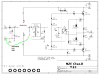
3. rebuilt the active elements of the board - only thing that didn't change were the caps and resistors ( and edcor )
- powered up and could trim it down as before, no trouble.
- left it running for 4 hours and the offset was stable sub 1mV
- played music and noted an intermittent high static which was worse without an input connected
- powered it up yesterday morning , came up as before but offset was 3.4mV which I figured would change when hot
- left it running and checked on it about 40 minutes later only to find the negative channel on the smps was current limiting
nothing seemed obviously off ( fets not shorted to ground )
4. removed the daughter boards , replaced the fets again
- fired it up and the 2SJ201 started to fail , shut it all down asap
- the offset was sitting at 4V and the bias had just hit about 1A when this all started to go south and I shut it down.
I managed to find a few 2SJ201's and have them incomming , do I need to replace the EDCOR's? did the DC on their primaries cause some damage?
Do I need to get rid of the SMPS and go more traditional psu ?
This just seems like such a simple circuit that leaves little room for things to go wrong but I seem to have stumbled on something that keeps triggering the right channel to smoke and I have a hard time thinking that the simple act of swapping in a daughter board was to blame and suspect that timing was merely coincidental.
the other channel has continued to behave through all of this = it is now disconnected but when tested alone, it works fine
would greatly appreciate some direction from anyone with more experience in this regard. I do have a scope which I can dust off.
thx..dB
to recap events
1. built it up with the Norwood initially and had it running for days playing music and all seemed well.
2. built the Mountain View and tested it offboard to make sure it behaved and all seemed well.
- as noted in my previous post, right channel went south and blew the Toshiba 2SK1530
- replaced this and the amp came up but offset was not well - took about 5 mins to get down to around 20mV , trimmer didn't adjust it and it bounced about : -10 to +40mV
= I did some more digging and realized that there was about 500mV DC at the outout of the board which also fluctuated
replaced the daughter boards with Norwood and still had the same behavior with offset not settling down
3. rebuilt the active elements of the board - only thing that didn't change were the caps and resistors ( and edcor )
- powered up and could trim it down as before, no trouble.
- left it running for 4 hours and the offset was stable sub 1mV
- played music and noted an intermittent high static which was worse without an input connected
- powered it up yesterday morning , came up as before but offset was 3.4mV which I figured would change when hot
- left it running and checked on it about 40 minutes later only to find the negative channel on the smps was current limiting
nothing seemed obviously off ( fets not shorted to ground )
4. removed the daughter boards , replaced the fets again
- fired it up and the 2SJ201 started to fail , shut it all down asap
- the offset was sitting at 4V and the bias had just hit about 1A when this all started to go south and I shut it down.
I managed to find a few 2SJ201's and have them incomming , do I need to replace the EDCOR's? did the DC on their primaries cause some damage?
Do I need to get rid of the SMPS and go more traditional psu ?
This just seems like such a simple circuit that leaves little room for things to go wrong but I seem to have stumbled on something that keeps triggering the right channel to smoke and I have a hard time thinking that the simple act of swapping in a daughter board was to blame and suspect that timing was merely coincidental.
the other channel has continued to behave through all of this = it is now disconnected but when tested alone, it works fine
would greatly appreciate some direction from anyone with more experience in this regard. I do have a scope which I can dust off.
thx..dB
In theory, Nelson Pass's AC coupling capacitor "C2" prevents any possibility of DC offset from getting into the MOSFET output stage from outside. Then the lab tech adjusts trimmer pot RV1 to dial out the remaining offset.
You could do an "I am from Missouri and you have to prove it to me!" test, by physically removing the input stage daughter card, and then grounding the primary of the Edcor. A crocodile clip from the IPS output bolt, to the RCA input jack ground, would do the trick.
If you do this and the offset changes in any significant way, that suggests there is something really wrong with the transformer and/or the input stage and/or C2 itself.
Much more likely, removing the IPS and grounding the transformer primary will do absolutely nothing: the offset will not change in any significant way. That suggests there's something wrong with the output stage or with C2 itself.
It resembles the divide and conquer method of troubleshooting.
_
Attachments
It resembles the divide and conquer method of troubleshooting.
_
Thanks Mark
divide and conquer is exactly the approach I am on

- yes I did the crocodile clip trick to appease my own curiosity, I wasn't sure about "core saturation" and how that might impact the amp = I should have checked DC downstream of C2 , I was just a little disillusioned at that point and removed the amp off the bench to somewhere out of harms way
Hopefully I will stumble on the cause and be a happy camper once again
..dB
Although the TC004/TA004 BJTs have lots of great specs (and I just bought 100 pieces of each for my stash), I can't help but love the KSC3503/KSA1381 for its low base-collector capacitance: 3 picofarads. Maybe somebody will conduct a bake-off or shootout or listening tournament between them, one of these days.
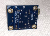
I niggled over that myself and used the KSC3503 in the 24mA version. It would be an interesting comparison that I'd like to make but the "Moffet-24" version will be the simpler test bed. It's a simple change: 3x J113's selected for 10 - 11 mA and the CCS set at 24mA. Q2 is jumpered from base to emitter. I used a "0-ohm resistor" so the jumper couldn't short to the collector pad.
I think I was overly optimistic about putting up schematics and data today - forgot Thanksgiving is right around the corner. Plus I'm still learning some new test gear and want to post some measurements with schematics.
Attachments
I suggest you call it a high current WHAMMY. An amplifier with so much active gain that negative feedback is required to tame and control it, and with a complementary MOSFET source follower output stage, and with Pass Labs' 4N35 optoisolator bias scheme for Class A operation. However your output stage bias current is increased by a factor of (10/0.47) = 21 times compared to the WHAMMY.
WHAMMY schematic (from Wayne Colburn's 2017 talk at Burning Amp) below. His front end gain stage was made from an IC rather than discretes. Most importantly, Wayne, like you, did not include an Edcor transformer in the signal path. This transformer is the distinguishing feature of the M2, in fact it is the DNA of the M2. Anything lacking the transformer cannot be considered part of the M2 family tree.
_
The whammy is not the genesis of this topology. Perhaps it should be called the Pass Opto-isolated bias circuit.
Patent:
https://www.passlabs.com/sites/default/files/pat_4752.jpg
M2 and Whammy are just two cases of Class A amps that use it.
PH104 -- I suggest you measure the bias voltage on each side of the nonpolar 220uF output capacitor on your Moffet Field PCBs. For the inboard side (sources of parallel JFETs), connect the meter with alligator clips so it's hands-off, and then watch the meter for the first 5 minutes after power on. I think you'll see the JFETs slowly warming up, and their Vgs values slowly changing as Vpinchoff changes with junction temperature, and Voffset sliding all over everywhere before thermal equilibrium is finally achieved. This would amount to five or ten minutes of DC offset applied to the Edcor primary, if the 220uF output cap were omitted. Me, I'm scared of DC magnetizing the transformer. And the de-magnetization procedure on Jensen Transformers's website, looks even scarier. Yikes.
Will do. I have the o/p caps off for now to make AC measurements and keep all DC off the transformer 'til I'm finished so measurement at JFET source is easy. Without making any specific DC measurements, the offset does wiggle around for a few minutes then settles to something under 100 mV.
At first glance there also appears to be an unexpectedly large difference between TC004B and KSC3503 which , if reproducible, I don't fully understand.
I dropped a box of assorted hardware last night and so have a mess to clean before doing anything fun......
At first glance there also appears to be an unexpectedly large difference between TC004B and KSC3503 which , if reproducible, I don't fully understand.
I dropped a box of assorted hardware last night and so have a mess to clean before doing anything fun......
...Me, I'm scared of DC magnetizing the transformer...
A few milivolts is unlikely to cause much problem, even if it did manage to slightly magnatise it, it probably wouldn't be audiable.
You could flip it round every six months to demagnatise or use a small fridge magnet to counter the magnetization

") maybe I'll start looking some MuMetal pieces from ebay.
maybe I'll start looking some MuMetal pieces from ebay.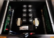
What would be the smallest size chassis to fit the M2x into? more interested in the height of the heatsink at 300mm long.
Would 142mm internal height be enough to cool without fans.
Have a look at 6L6's post in the M2 thread where he says:
"A 3U 300mm is just on the edge of being too small. 3U 400 would be fine. 4U 300 is considered normal."
- Home
- Amplifiers
- Pass Labs
- The diyAudio First Watt M2x