I do have a box or two of tested ones that I can send to the store.
That would be great!
I do have a box or two of tested ones that I can send to the store.
Thanks so much! That is an amazing gesture! 😊
M2x documentation on Google Drive
I don't feel like burning 30 CD-ROMs and I sure don't feel like buying 30 USB thumb drives, to mail out M2x documentation to the 30 people who bought PCBoard sets. So instead I gathered up all the documentation and put it into a .zip archive on Google Drive. I invite buyers to download it and save the data to a thumb drive, or to the cloud, or wherever they like best.
This consists of the full schematics, full Bills Of Materials, and Notes To Builders of all the boards. I extracted it from various messages sprinkled through this thread, and consolidated it all into a single handy .zip file. The download link is DELETED. See post #1 for most current documentation.
Search keywords: Google Drive Documentation Nortwangler
Nortwangler is a nonsense word whose only purpose is to help the diyAudio search engine find this one single post. Whenever somebody asks "Where's the documentation for M2X?" I can reply in all seriousness: "Search for Nortwangler !"
Beware: there's no preview. Zip archives don't have previews. Just download it to your hard drive and be happy.
Last edited by a moderator:
So instead I gathered up all the documentation and put it into a .zip archive on Google Drive. I invite buyers to download it and save the data to a thumb drive, or to the cloud, or wherever they like best.
This consists of the full schematics, full Bills Of Materials, and Notes To Builders of all the boards. I extracted it from various messages sprinkled through this thread, and consolidated it all into a single handy .zip file. The download link is
Search keywords: Google Drive Documentation Nortwangler
Nortwangler is a nonsense word whose only purpose is to help the diyAudio search engine find this one single post. Whenever somebody asks "Where's the documentation for M2X?" I can reply in all seriousness: "Search for Nortwangler !"
Excellent! That way, it can be updated as needed. The gratuity of 6L6, Nelson Pass and yours truly is most sincerely appreciated!
Best,
Anand
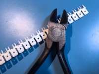
Examples of the items mentioned in post #3, section 1:
Possibly useful examples of low price & unknown quality M3 fasteners
~
- Reel of blade connectors and large "dykes" side cutting pliers: see Figure 1 below
- Cheap but useful metric nut driver set: Amazon link 1
- Bourns H-90 plastic screwdriver: Mouser link
- M3 bolt assortment: Amazon link 2
- M3 star washers: Amazon link 3
~
Attachments
With different front buffer circuit, can I raise the psu voltage to +/-35v? I have read somewhere that the Jfet pairs prevents us from using more than 25v.
You could, but the commensurate amount of dissipation in the power FETs would be exciting. I suppose you could drop the bias amount, but to what end?
You could, but the commensurate amount of dissipation in the power FETs would be exciting. I suppose you could drop the bias amount, but to what end?
It's not that I need an extra power, I just have 25ac trafo laying around unuse. I will give it a try an see if the sinks can accommodate that.
It would be a challenging project. Off the top of my head, I can think of a few things that would need to be changed.With different front buffer circuit, can I raise the psu voltage to +/-35v? I have read somewhere that the Jfet pairs prevents us from using more than 25v.
{1} You'd need a bigger heatsink, about 40% bigger, since the output stage current would remain the same but the power supply voltage is increased by 40%.
{2} You'd need to drive the amplifier with a bigger input swing. M2 is a no-feedback design with fixed gain. The gain is completely determined by the choice of (Edcor) transformer. Today to get full rated output power of a stock M2 with ±25V supplies, you need to apply 3V RMS to the input. Increasing the supply voltage by 40% means you'd need to apply at least 4.2V RMS at the input in order to get full power output. Not many preamps provide a 4.2V RMS output swing.
{3} You'd need to create a new input stage circuit design, capable of withstanding ±35VDC supplies. None of today's M2x input stages would survive ±35VDC supplies, and that includes "Ishikawa" the Nelson Pass original. Fortunately you've got all the information you need to create your own brand new input stage PCB, including the physical dimensions shown on a drawing earlier in this thread.
{4} You'd want to carefully scrutinize the M2x amplifier board circuit design, and decide whether you need to increase the voltage rating of any of the components. Starting with the electrolytic capacitors, both polar and nonpolar.
{5} If I were to make a wild and unreliable guess, I'd speculate that the "Tucson" circuit might be the one that would require the least modifications / easiest modifications, to make it operate correctly with ±35VDC supplies and not catch on fire. The others are probably more difficult, likely involving life threatening surgery or total redesign. Want the original Nelson Pass M2 sound (Ishikawa)? Sharpen up your design pencil and put fresh batteries in your calculator.
Last edited:
Speaking of blasphemous heresy (post #3), the parts kit I shipped to 6L6 so he could build a complete M2x amplifier and photograph the process for his Build Guide, did include the non-Biblical values R6=37K and RV1=20K. He built it (just look at the photos!) and was able to dial offset down to zero, as desired. Amp sounds great too.
Nearest E96 standard value is 37.4K , nearest E48 standard value is 36.5K . Both are perfectly fine.
Nearest E96 standard value is 37.4K , nearest E48 standard value is 36.5K . Both are perfectly fine.
Nobody will be burned at the stake, as the circuit needs more DC offset adjustment range than as originally published - I helped a local builder with his M2 project built on the excellent Tea-Bag PCB, and it also needed the pot and resistor changed to get the offset set to zero.
It's no big deal.
It's no big deal.
- Home
- Amplifiers
- Pass Labs
- The diyAudio First Watt M2x