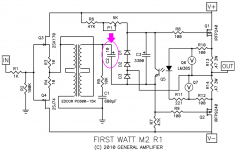
Attached below is the original First Watt M2 schematic, with "C2" circled. In this schematic, C2 acts as an AC coupling capacitor between R5 and D3. Is that the capacitor you are talking about? Does M2X have a 220uF capacitor between R5 and D3?
_
_
Attachments
Manniraj - Bias is automatic, DC offset is controlled by the only potentiometer on the main board.
The output stage works beautifully without a daughter card attached.
The output stage takes a long time (about 90 seconds) to charge the 3300uF cap and get to proper operating points.
One channel at a time is always a good idea.
The output stage works beautifully without a daughter card attached.
The output stage takes a long time (about 90 seconds) to charge the 3300uF cap and get to proper operating points.
One channel at a time is always a good idea.
The output stage works beautifully without a daughter card attached.
So, I could drive pin 1 of the Edcor with the B1-Korg preamp, sans normal input circuit.
")
I don't see why not...
I will give it a try, someday.
I have the Edcors but nothing else.
Thanks.
I fully agree with 6L6 -
the M2X poweramp is well worth every minute to build it!
Greets
Dirk
Totally agree.
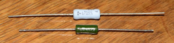
I have two types of .47 ohm 3W power resistors. The usual Panasonic MOX type and Vishay wire wound glazed type that is a bit more robust and has lower temp. drift (75ppm/C vs. 300 ppm/C). When I measure on a bridge they have about same data up to 100 kHz. The wire wound has a bit lower serial inductance…...which was a bit surprising….but noting to "talk about". You prefer the MOX type as source resistor for the output mosfets for subjective "audio" reasons?
Attachments
It's a math problem. We know that (8 / X) equals 20 and we wish to solve for X.
(8 / 0.1) equals 80 ... too high!!
(8 / 1.0) equals 8 ... too low!!
Since X=0.1 gives an answer that's too high, while X=1.0 gives an answer that's too low, we know for certain that the correct value of X is somewhere between 0.1 and 1.0. Maybe that's all we really need.
Also try X=0.4 and X=0.5.
LOL, I made the equation the wrong way, so we got 0.4
I think deafbykhorns is referring to C1 on Ishikawa.
That capacitor is talked about in the .pdf in post #1, as well in the thread on post #2 and #4.
(Dont install it and just use a bit of wire if you like.)
That's exactly what I was looking for, wasn't sure why it was used except to protect the Edcor. Couldn't 220uf cause some phase shift or should be calculated on output impedance of source?
Last edited:
Manniraj - Bias is automatic, DC offset is controlled by the only potentiometer on the main board.
The output stage works beautifully without a daughter card attached.
The output stage takes a long time (about 90 seconds) to charge the 3300uF cap and get to proper operating points.
One channel at a time is always a good idea.
Thanks Jim, my question was more towards should i keep the daughter card when I first power on? I can just look at the offset alone after power on as you said that Bias is automatic which is very good.
For the 0.47 ohm 3 Watt output resistors named "R13" and "R14" in Nelson Pass's Original M2 Schematic (identical resistor IDs in the M2x MainAmp schematics attached to post #1 of this thread),
the key thing to do is buy close tolerance (5% or better) in a 3 watt rated resistor, while still fitting into the footprint that's on the M2x PCB. I suggested KOA Speer Metal Oxide resistors (link to Mouser sales page) because they're cheap and plentiful and meet the criteria above. Oh and they're also not wirewound, so I don't have to listen to the same old tedious arguments about the stupidity or wisdom of using WW resistors in that position. If diyAudio members want to "discuss" (argue) about wirewound resistors, please go right ahead with my blessings, but I won't be participating.
I will say that for a completely different project which is not named M2x, I've selected Vishay "PR03" 3 Watt Metal Film (not metal oxide) resistors, because they are a little better thermally. Their thermal resistance theta, in degrees C per watt, is a wee bit lower than the KOA Speer Metal Oxide resistors linked above. But this might be totally irrelevant for the M2x since R13 and R14 on the M2x MainAmp board don't feel warm when I touch them. Do they feel warm when YOU touch them?
If you have the expertise and the equipment to measure 0.47 ohms, plus or minus 0.005 ohms, then I suggest you buy more than 4 pieces of those resistors, they only cost 25 cents each. Then select matched pairs for each amplifier channel. This cannot possibly hurt, and it might possibly help in some way, so: why not do it??
Ok....I will try to match two 0.47 ohm 3W resistors. I don't think I will be able to hear any difference between different technology resistors. Some may even like carbon resistors. Often 5% resistors are much better than 5%. It is probably hard to make them so different with todays production methods. I have a HIOKI LCR tester I can use for matching.
Here is a Mouser link that will work better:
MOSX3CT631RR47J KOA Speer | Mouser
Mark's was for a 4.7 ohm resistor, and mine is (I think) for a .47 ohm resistor.
MOSX3CT631RR47J KOA Speer | Mouser
Mark's was for a 4.7 ohm resistor, and mine is (I think) for a .47 ohm resistor.
Last edited:
I always buy a few more resistors and choose those ones which are closest
to each other. But I don't get them always matched to below 1% or better 0.1%.
Sometimes I ask myself if my FLUKE DMM is measuring exactly enough?
Hi Dirk,
for matching (not necessarily exactly measuring) resistors of a really low ohmic value, just string a bunch of them in series and connect the string to your lab supply, set to a rather arbitrary value.
Then, just compare the voltage drops across each resistor and choose the respective closest values.
DMMs are notoriously inaccurate at measuring low resistances - you would need a Wheatstone bridge for that. On the other side, DMMs are very good and very precise / repeatable at measuring tiny DC voltages ...
And you also really only need a relative measurement, not an absolute one for matching resistors.
Best regards, Claas
Perhaps the Mtn View boards have a more organic sound quality to them [than Ishikawa], but it is really difficult to tell exactly what is different besides the imaging. This is good news, as it indicates that there is at least one discrete transistor implementation of an input stage that is a viable and worthy replacement for the increasingly expensive and occasionally tricky to source k170/j74 JFets used in the original M2.
... I do have some ideas for [circuit modifications] that might be made, and will eventually report on those after I've had a chance to build up to prototype vero boards and listen to them for a while.
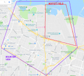
One member here built a super modified Mountain View using multiple parallel JFETs and other prestidigitation. It was called Moffett Field and appears somewhere in this thread, search may locate it. The builder felt it was sonically superior to the original Mountain View.
The etymology of the name is pictured below. At the top in blue, is the San Francisco Bay.
_
Attachments
- Home
- Amplifiers
- Pass Labs
- The diyAudio First Watt M2x