Hello the experts , I find IRF240 and 9240 is in TO-3 package. I want use it and get larger power deliver. However i need to mount it on additional heatsink with short wire. Anyone try it ?
And if use this amp drive my speaker which is 85dB. Can this amp able do it well.
Last question, if i install 2 pairs power irf240&9240s per channel. Does the board able to support it ? Any things need to be mod?
And if use this amp drive my speaker which is 85dB. Can this amp able do it well.
Last question, if i install 2 pairs power irf240&9240s per channel. Does the board able to support it ? Any things need to be mod?
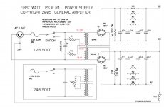
A correctly working M2 or M2x amplifier, using a standard First Watt power supply such as the one below, performs an ... interesting ... set of behaviors when you connect it to a dim bulb tester and turn it on.
Has anyone actually tried this experiment? Could you let everybody know what happens, so that new builders will have an idea about what to expect?
_
Has anyone actually tried this experiment? Could you let everybody know what happens, so that new builders will have an idea about what to expect?
_
Attachments
Hello the experts , I find IRF240 and 9240 is in TO-3 package. I want use it and get larger power deliver. However i need to mount it on additional heatsink with short wire. Anyone try it ?
Yes, that will work well.
And if use this amp drive my speaker which is 85dB. Can this amp able do it well.
Very well. You'll be pleasantly surprised.
Last question, if i install 2 pairs power irf240&9240s per channel. Does the board able to support it ? Any things need to be mod?
Do not do that.
A correctly working M2 or M2x amplifier, using a standard First Watt power supply such as the one below, performs an ... interesting ... set of behaviors when you connect it to a dim bulb tester and turn it on.
Has anyone actually tried this experiment? Could you let everybody know what happens, so that new builders will have an idea about what to expect?
_
For me, if memory serves correctly when initially turning on the amp the bulb lit up brightly as the inrush current charged up the capacitors in the powers supply and then dimmed back down. Then, about 30-45 seconds after that as the auto-bias circuit of the M2-X amp began raising the current draw of the amp channels and charging the 3300uf cap, the bulb began to turn brighter once again.
Same behavior for me.
it had given me some sweat.
but the responses from the forum had indicated to me that this behaviour was normal.
So I had removed the bulb test and adjusted the offset.
Since, I drink cognac while listening to music!
I just reread my notes:
If the PSU card is not connected to the main cards, the bulb test lights up for 5s and then turns off.
PSU card connected to the main cards, the bulb test lights up gradually after 30s of operation.
On step 5 of my testing where I have powered up through the PSU board. Dim bulb tester worked as shown in youtube vids. However, I am scared until I understand what output of the PSU should show on DMM. When I attach it to V+ and V- output side of PSU I get 57 Volts DC which seems high. I do not want to blow anything on the M2 boards. Any advice is, as always appreciated...
Also wondering how long it takes for the LEDs to dim to off? The DMM is showing only a .1 volt decrease per second..
Thanks
Also wondering how long it takes for the LEDs to dim to off? The DMM is showing only a .1 volt decrease per second..
Thanks
Assuming you used a 18-0-18 transformer, you 36V * srt(2) = 50.9V peak to peak.On step 5 of my testing where I have powered up through the PSU board. Dim bulb tester worked as shown in youtube vids. However, I am scared until I understand what output of the PSU should show on DMM. When I attach it to V+ and V- output side of PSU I get 57 Volts DC which seems high. I do not want to blow anything on the M2 boards. Any advice is, as always appreciated...
Also wondering how long it takes for the LEDs to dim to off? The DMM is showing only a .1 volt decrease per second..
Thanks
It will run a bit high with no load, and will run even higher if your local voltage is on the high end. If you put a 150W bulb in your tester, you can be pretty stupid about hook up and probably not hurt anything. I used a 150W bulb because I am prone to being stupid
")
I used 4x22KuF caps per rail on mine, and with a 22k bleeder, it would take about 45 minutes to bleed off. I replaced it with a 4.7k resistor. Once you hook up the boards, it will bleed off much faster. Mine drains in under 10 seconds, so I will probably put the 22k's back in when I replace the PS in the near future.
until I replaced the bleeder, I would just short the PS with an 8ohm 100W resistor.
EDIT:
I also used 35V caps. No issues with a 3A fuse, and I am also running a second small transformer to run the fan and micro controller I added for temperature monitoring.
Last edited:
It was recommended to hook only one channel to the PSU at a time for testing. If that is done, will the higher voltage I am reading be any problem? I am understandably cautious to hook the M2 boards to anything which lets the smoke out.
My method I am going to use is to only hook up ONE M2 channel board and test as follows:
a) PSU V+, V-, and GND to M2 amp board VPOS, VNEG, & both GND.P points.
b) RCA jack center to M2 board INPUT and RCA outer barrel to M2 board GND.I
c) Speaker channel red to M2 OUTPUT and black to M2 GND.O or PSU ground for potentially less hum?
Short out RCA Inputs and test at speaker, dialing RV1 to hit zero volts.
I used 35V 22000uF for the caps - is this too high for the M2? any concerns or corrections I need to make?
No, 35 volts isnt too high. Use 50 volts, fine, but more expensive. dont use too low.
Hook everything up with amp ready to go. Hook one side to power supply, I ramp up with variac, safer to use Dim bulb too.
Btw, if you haven't tested power supply alone yet, do power supply first with no amp hooked up. If passes dim bulb, power down, remove dim bulb, test power supply alone again. Voltage will be a little high because no load.
Hook dimbulb back up and power one side. If passes, unhook and hook up other side try it with dim bulb. if it passes, remove dimbulb and hook up both, bring up with variac. Never adjust offset or bias (no need to set bias here, optocoupler does that.) with dimbulb in place. Slowly power up with variac sans dimbulb measuring bias to make sure all is good on both sides, set offset and let burn in. remeasure, re do offset and listen.
Russellc
Last edited:
It was recommended to hook only one channel to the PSU at a time for testing. If that is done, will the higher voltage I am reading be any problem? I am understandably cautious to hook the M2 boards to anything which lets the smoke out.
My method I am going to use is to only hook up ONE M2 channel board and test as follows:
a) PSU V+, V-, and GND to M2 amp board VPOS, VNEG, & both GND.P points.
b) RCA jack center to M2 board INPUT and RCA outer barrel to M2 board GND.I
c) Speaker channel red to M2 OUTPUT and black to M2 GND.O or PSU ground for potentially less hum?
Short out RCA Inputs and test at speaker, dialing RV1 to hit zero volts.
Lets back up a bit and make sure nothing got left out.
First, do you have a single safety capacitor across the AC mains where it enters the terminal block?
Are you using a pair of thermistors to provide power to the second set of primary wires in the transformer?
Early in the thread is a nice pic of this set up, and it is in the schematic for the generic Pass Power supply. If you do not have these, you might have issues with the fuse blowing.
Have to placed a thermistor between the PS ground and chassis ground? This will "raise" the PS ground above the noisy ground floor of the AC mains. Yo can run the amp with out it, but you might get hum.
Sorry if I am asking "stupid" questions, these particular items are not discussed in this thread until it came up later when someone was having issues with their amp.
Next for hook up, I suggest doing this:
Install both boards.
Verify that the power inputs are not shorted to ground with a multi meter. You should also check other spots on the board if you can figure out which ones. If not, just use the bulb tester when you put power to the boards.
Do check for a short between all three legs of each mosfet and the heatsink.
Hook up V+,V-, and PS ground to channel A, turn on the power and look for smoke.
If you use the Mountain View board, it has a LED that will warm your heart when it glows.
If all is good, short the input (power it off first), and start tweaking the DC offset. Give it 20 minutes or so, and tweak it again. Put the probes directly on the speaker outputs of the board, not at the speaker end of the speaker wire (binding posts really should not be connected yet, especially if they are not insulated).
Turn off the amp, disconnect Channel A, and hook up channel B.
repeat the above process.
Power off, hook up channel A, and let it warm up for a couple of hours. Once your DC offset is stable and as close to zero as you can get it, put an 8ohm 100W resistor across the speaker terminals, and do a final offset. I found the resistor made no difference, but it made me sleep better
My amp needed a small tweak 24 hours later, and has been dead stable ever since.
Once all that is done, then hook up the speaker terminals. I used an old pair of speakers to make sure it was working, then hooked it up to my mains speakers.
On the subject of hum and where to put the speaker ground. If moving the ground off the board and onto the PS reduces hum, there is probably some ground loop. A likely place for the ground loop is the speaker terminals. If they are not insulated, then you will almost for sure have a ground loop. My speakers are grounded to the board, and I have no hum at all.
So how important is it to have a Variac? Many talk about it like it is a given that everyone has one.
I am pretty sure there is no such thing as a variac.
It is like a 2x4 stretcher, something you send a newbie off to find.
My brother might have had one decades ago.
Probably easier to find someone that will admit to buying a Bee gees album that finding someone to admit that they own a variac
If the bulb went out on the bulb tester, then a variac will not gain much.
I did check the offset with the bulb tester hooked up just to make sure it was not way out of wack. That is simple prudence imo.
Variacs exist:
https://uk.farnell.com/c/transformers/variable-transformers
https://uk.farnell.com/c/transformers/variable-transformers
seems like folk are still having fun. I do own a variac ( and yes it is really old ) but it would not be much good for the M2X - the current bias mechanism ramps up slowly and a variac would not help much aside from ensuring that the rail voltages came up normally - which in itself is no small thing.
my method - correct or not, was to check, check and check again that all connections were as they were supposed to be, checked for shorts to ground and ensured the supply voltage was what it should have been . then using as many cheap multimeters as I could find, hooked them up to everything I thought important to measure with power up
- rails
- bias current / voltage
- DC offset
had a small screwdriver ready to adjust offset , before power up set it to the midpoint
If DC offset drifted beyond 200mV, I dialed it in as the bias came up. (probably not necessary but I wouldn't let it drift too far )
so initial start up = bias will be zero as no current will flow with cold FETs, if rail voltage is not close to +-24V - shut it down asap , if rails come up OK, then watch bias and DC offset, my bias starts picking up after about 20 seconds from cold.
but I have blown a few pairs of mosfets, so ..pinch of salt ... although I would argue not entirely my fault.
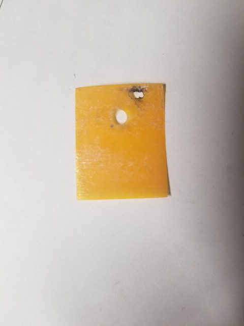
This is the aftermath of the arc caused by a pinhole in the thermal pad which resulted in shorting the mosfets to ground and has been the bane of my build. I have now replaced all pads with ceramic and the amp was successfully bench tested for 48 hours and is playing beautiful music once again.
..dB
my method - correct or not, was to check, check and check again that all connections were as they were supposed to be, checked for shorts to ground and ensured the supply voltage was what it should have been . then using as many cheap multimeters as I could find, hooked them up to everything I thought important to measure with power up
- rails
- bias current / voltage
- DC offset
had a small screwdriver ready to adjust offset , before power up set it to the midpoint
If DC offset drifted beyond 200mV, I dialed it in as the bias came up. (probably not necessary but I wouldn't let it drift too far )
so initial start up = bias will be zero as no current will flow with cold FETs, if rail voltage is not close to +-24V - shut it down asap , if rails come up OK, then watch bias and DC offset, my bias starts picking up after about 20 seconds from cold.
but I have blown a few pairs of mosfets, so ..pinch of salt ... although I would argue not entirely my fault.
This is the aftermath of the arc caused by a pinhole in the thermal pad which resulted in shorting the mosfets to ground and has been the bane of my build. I have now replaced all pads with ceramic and the amp was successfully bench tested for 48 hours and is playing beautiful music once again.
..dB
I am pretty sure there is no such thing as a variac.
It is like a 2x4 stretcher, something you send a newbie off to find.
My brother might have had one decades ago.
Probably easier to find someone that will admit to buying a Bee gees album that finding someone to admit that they own a variac
If the bulb went out on the bulb tester, then a variac will not gain much.
I did check the offset with the bulb tester hooked up just to make sure it was not way out of wack. That is simple prudence imo.
They indeed exist, and are extremely useful. They are still made and easy to find from various suppliers. I still have one from tube building days, and properly used can prevent many misfortunes if you are familiar with their use. I usually depend on one these days without a dimbulb. Using multimeters on every important junction, you can spot trends in proper fire up of these amps and tell early on if something isnt right.
That said I have done many of the builds here and am very familiar with the use of one and find them indispensable. That said, the dimbulb can save things a variac wont. On one of my BA3 builds I miswired the power supply to the board and kept ramping up when I should have stopped and cooked the 4 mosfets on the front end board...a dimbulb would have saved the day, but it was a cheap repair. Too tired that night and wanted to finish to quickly.
They can really help in Firstwatt amps where the bias must be set. You can catch it going too high early if pots are not set properly from the get go. Here, the bias is set by auto coupler, but I also watch for anything getting to warm too quick.
Just because you are not familiar with them or their use is no need to discount them. Many, many builders here use them.
Russellc
Last edited:
- Home
- Amplifiers
- Pass Labs
- The diyAudio First Watt M2x