I thought I would try the Norwood daughter board and already received the parts. After trying my beginner hand at some practice surface-mounting, I am [re-]thinking I better build up the Mountain View or Austin first. Since I am re-ordering... Anyone have experience with either they care to share? Furthermore, with the resistor values in BOM, are the all 1/4 (.25) W?
Mountain View and Tucson weren't that hard to solder. Just read the instructions for Mountain View first before you do it. I am missing parts for the other three boards.
I had the same issue with RV1, if you hook 2 pins, you can rock it into the 3rd and the pins will form with no issue.
Get a magnifying head set. I have this thing, dunno what the current model is, but it is worth it's weight in gold.
Amazon.com: Bausch & Lomb Magna Visor with Lens Set: Health & Personal Care
A small chisel point or beveled point iron is good. The typical pointy iron is about useless for SMD. Use lots of flux. I use a flux pen, but I think a tube would be better. Watch some YouTube videos.
The resistors are not too big. I ordered all the parts before the boards arrived, and all my resistors are 1/4W since the BOM didn't advise buying 1/8W. just mount them at an angle.
I thought I would try the Norwood daughter board and already received the parts. After trying my beginner hand at some practice surface-mounting, I am [re-]thinking I better build up the Mountain View or Austin first. Since I am re-ordering... Anyone have experience with either they care to share? Furthermore, with the resistor values in BOM, are the all 1/4 (.25) W?
Get a magnifying head set. I have this thing, dunno what the current model is, but it is worth it's weight in gold.
Amazon.com: Bausch & Lomb Magna Visor with Lens Set: Health & Personal Care
A small chisel point or beveled point iron is good. The typical pointy iron is about useless for SMD. Use lots of flux. I use a flux pen, but I think a tube would be better. Watch some YouTube videos.
The resistors are not too big. I ordered all the parts before the boards arrived, and all my resistors are 1/4W since the BOM didn't advise buying 1/8W. just mount them at an angle.
Attachments
I always keep the schematic handy when populating PCB's. See post #1 in this case.Is it true that C0, C1, CB3 do not have a specific polarity? i.e. they can be put in either direction?
If there is no '+' marker next to a capacitor, it means that it is non-polarized.
Thanks
Is it true that C0, C1, CB3 do not have a specific polarity? i.e. they can be put in either direction?
It's true that polarized electros in the signal path should be avoided as much as possible.
I remember there was some research done years ago about electrolytic caps and Bi-polar caps and the conclusion was that Bi-polars were always better despite the fact that they are 2 electros back to back.
The famous Black Gates were Bi-polar caps.
I find a lot of BP (NP) caps in crossovers of old organs, mostly Nippon Chemicals or Nichicon.
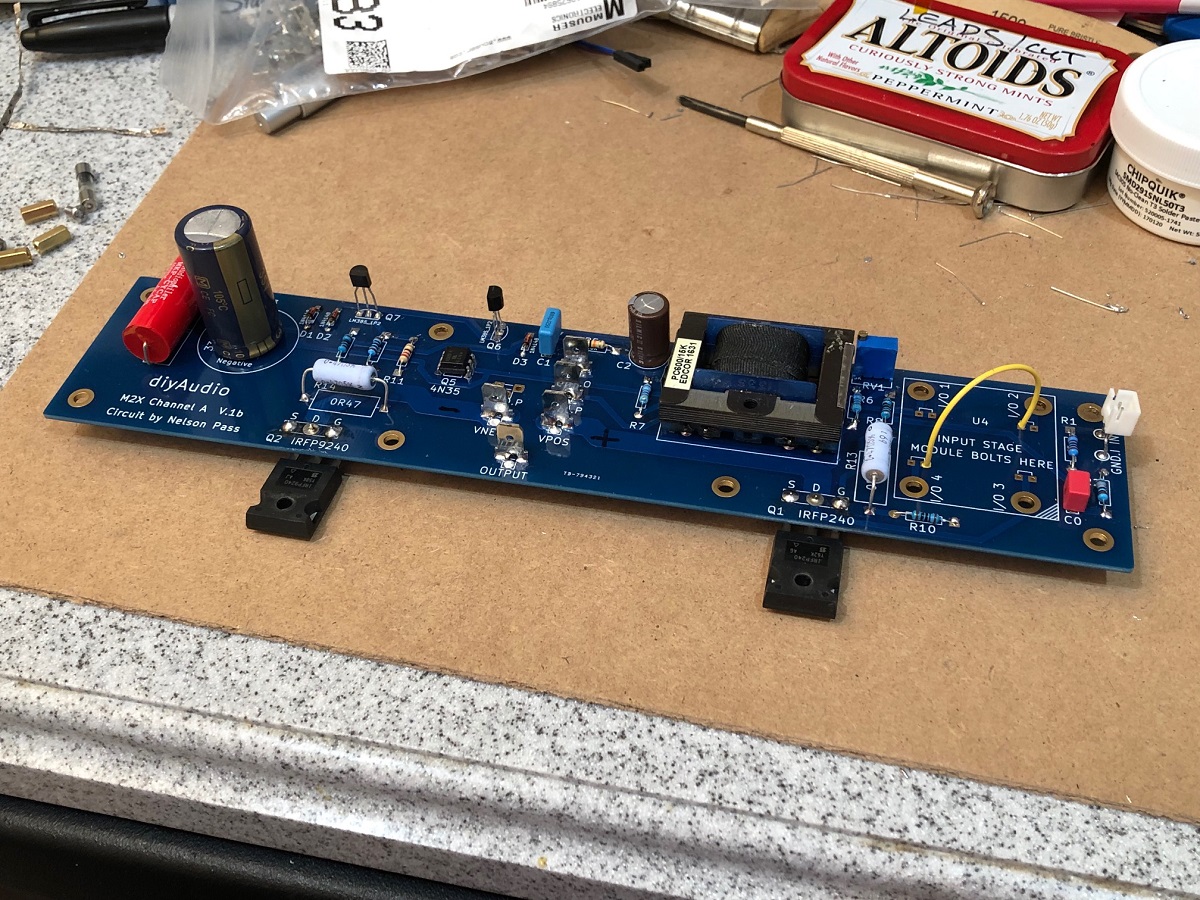
In preparation for testing the Melbourne daughterboards when they come in, I got an M2X board-set and built up the main board. Since I don't have any daughterboards yet, I just put a jumper from pin 2 to 4 and then will drive it with an external Aksa Lender preamp. I put the Edcor in though.
The DC offset is rather high and I could not get it any closer to zero than -0.187V. I seem to recall having to make R7 equal to about 56k on my previous Teabag M2 in order to get the offset to zero out - is that right? I am testing it out with a speaker and it plays music.
The 4N35, LM385, and MOSFETs are lifted from the Teabag M2.
Attachments

Last edited:
Regarding offset-
The heretical modification you speak of is note# 3 on post #3:
The diyAudio First Watt M2x
and some discussion on offset adjustment beginning here:
The diyAudio First Watt M2x
The heretical modification you speak of is note# 3 on post #3:
The diyAudio First Watt M2x
and some discussion on offset adjustment beginning here:
The diyAudio First Watt M2x
Regarding offset-
The heretical modification you speak of is note# 3 on post #3:
The diyAudio First Watt M2x
and some discussion on offset adjustment beginning here:
The diyAudio First Watt M2x
Thanks, it looks like it recommends leaving R7 alone and changing ratio of R6 and pot. That’s more work but ok.
I have a question about Tucson bird for Mark Johnson:
Consider building two sets of Tucson boards. I don’t see any good reason why you shouldn’t build two Tucson boards with OPA604 thru‐hole opamps, and then build two more Tucson boards with OPA1611 SMD opamps. Listen to both in your M2X; which opamp sounds best to you? Check the diyAudio “Swap Meet” forums, there is probably a thriving aftermarket for individual M2X daughter boards. People buy a full set of ten daughter boards, use four of them, and then decide to sell or trade the others.
The spec sheet for opa1611 says +/-18v max supplies. Isn’t the power rail for the M2X DB’s +/-24v?
http://www.ti.com/lit/ds/sbos450c/sbos450c.pdf
I have a bunch of them and could try it out but for fear of blowing them out.
There's nothing heretical about it... ") I've found over the years and through building many of these amps (*) that Papa must have a full drawer of some pretty darn centered transistors, who's operating points are usually right down the middle of the specification.
I've found over the years and through building many of these amps (*) that Papa must have a full drawer of some pretty darn centered transistors, who's operating points are usually right down the middle of the specification.
Because of that, his amps don't need a ton of adjustment to get the offset and balance set and nulled.
But since everybody else building them isn't a jolly old elf with a direct line to Santa for parts, having a bit longer/wider resistance range for adjustment is very helpful for all builders.
(*) Thinking about it, my first F5 needed a ton more resistance to bias properly, the BA-3 needed an adjustment like this to give more range to the pot on the output stage, in addition to using a bigger pot on the input stage. The F6 needed a higher value zener than the original spec, etc... The reason for this has to do with the majority of these amps being direct coupled and the Idss of the input stage transistors in turn effects the voltages to get the Vgs of the next stage mosfets to turn on. This is neither bad nor good, merely the effect and interplay of your amp's particular transistors, and completely normal.
I.E., more adjustment range only helps the amp operate properly.
I've found over the years and through building many of these amps (*) that Papa must have a full drawer of some pretty darn centered transistors, who's operating points are usually right down the middle of the specification. Because of that, his amps don't need a ton of adjustment to get the offset and balance set and nulled.
But since everybody else building them isn't a jolly old elf with a direct line to Santa for parts, having a bit longer/wider resistance range for adjustment is very helpful for all builders.
(*) Thinking about it, my first F5 needed a ton more resistance to bias properly, the BA-3 needed an adjustment like this to give more range to the pot on the output stage, in addition to using a bigger pot on the input stage. The F6 needed a higher value zener than the original spec, etc... The reason for this has to do with the majority of these amps being direct coupled and the Idss of the input stage transistors in turn effects the voltages to get the Vgs of the next stage mosfets to turn on. This is neither bad nor good, merely the effect and interplay of your amp's particular transistors, and completely normal.
I.E., more adjustment range only helps the amp operate properly.
Thanks, just saw that too once I looked at schematic of DB. +/-14v rails on the opamp then.
Has anyone ever noticed that on the main board schematic, the arrows point the wrong way on the output MOSFETs? N chan is towards Gate and P is away, usually. No matter, they are labeled accordingly.
Has anyone ever noticed that on the main board schematic, the arrows point the wrong way on the output MOSFETs? N chan is towards Gate and P is away, usually. No matter, they are labeled accordingly.
Last edited:
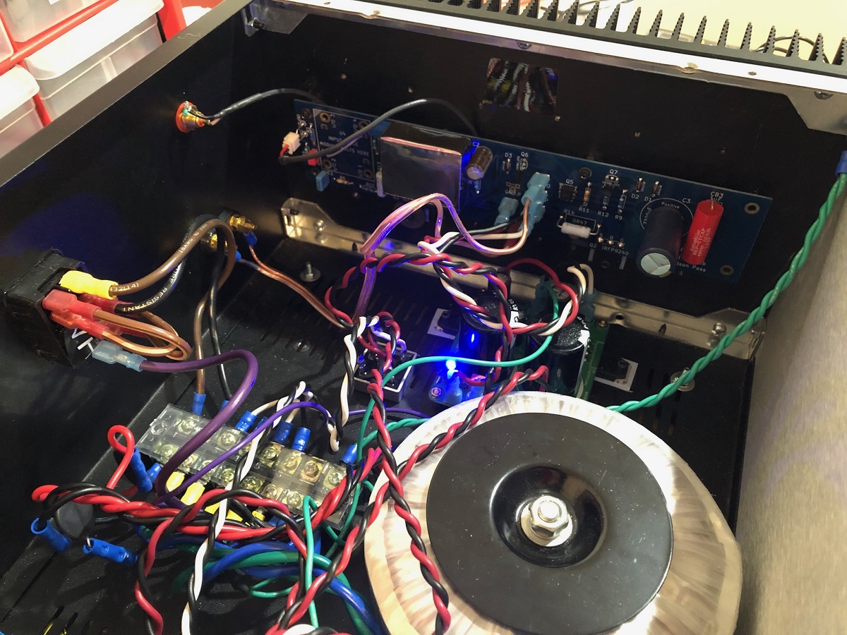
I went in and modified the DC offset trim setup with a 39k pot on R6 and 10k pot on VR1. I did not have any 20k pots left so hopefully this gets close enough.
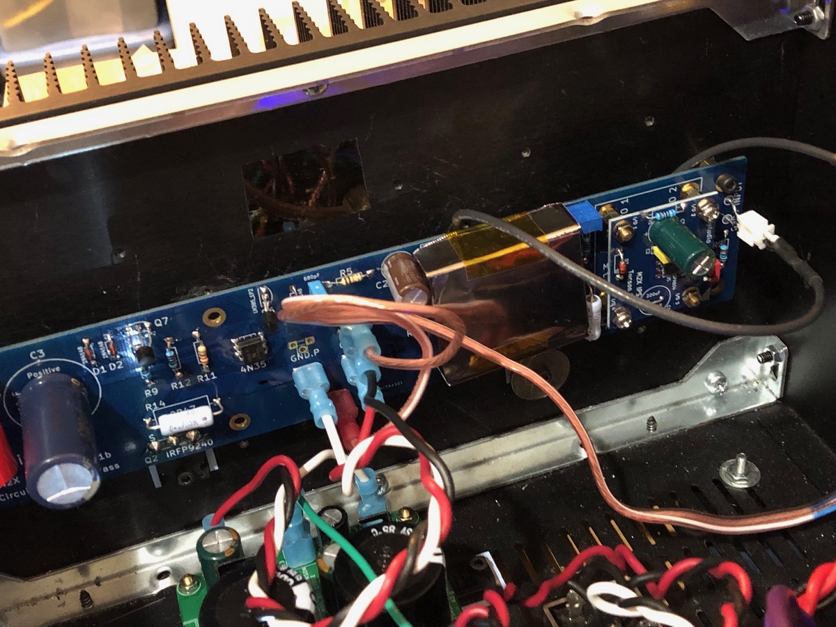
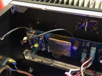
I also wanted to try out one of Mark Johnson's DB's and decided on the Tucson since it looked easiest and I have OPA1611's on hand already. A tiny dab of solder paste and hot air gun and 6 other parts and they were done. I am DC coupling this opamp to the Edcor, hopefully DC offset should not be a problem. Now need to install back on amp. My voltage rails are only about 20.2v (due to sag and also 2v drop from cap multiplier supply), so I am using 4.3v Zeners. Should give me circa +/-16v rails for OPA1611, well within +/-18v limit.
Some photos:
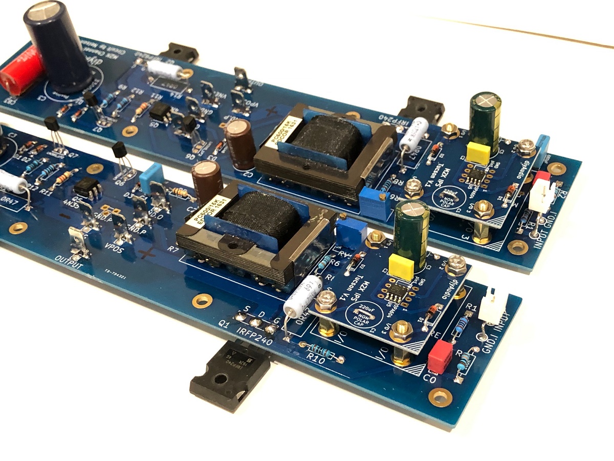
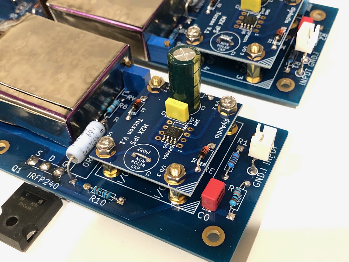
Attachments

Last edited:
That looks great!!
Did you post any info on the transformer shields? I like the look of them.
Yes, here:
https://www.diyaudio.com/forums/pass-labs/281520-official-m2-schematic-311.html#post5569239
Nitto No. 597B Mu-Metal (Ultraperm 80) sheeting formed into a 44mm L x 35mm W x 16mm deep rectangular cover, Self stick foil metal. Since I removed the Edcors from Teabag to this board, I had chance to add a mini belly-band across the bottom in addition to the box over the top. I put some polyimide tape (Kapton) on edges of foil band to prevent possibility of shorting with pins on Edcor.
Last edited:
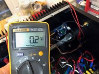
Testing the Tucson (with OPA1611 at +/-15.7v rails). It worked just fine the first time and it sounds very good. A nice ultralow THD and noise front-end reference based on the specs of the OAP1611, I am not sure something in a small low price opamp exists that is lower noise and lower THD. The noise measured at the amp output with source volume turned to off shows 0.2mV rms (on Fluke101). I do not hear any hum with one RCA connected but have hum with both RCA inputs connected. I suspect it is the single power trafo with dual cap multipliers for each channel is causing a 2mV at the output ground loop.
So I have verified that my M2X setup works with a DB, and ready to build and test Melbourne as soon as boards arrive tomorrow.
Right channel:
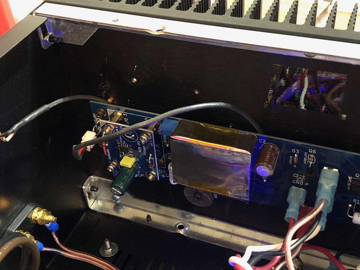
Left channel:
Noise measurment with FLuke 101:

So I have verified that my M2X setup works with a DB, and ready to build and test Melbourne as soon as boards arrive tomorrow.
Right channel:
Left channel:
Noise measurment with FLuke 101:
Attachments

Last edited:
That looks great!!
Did you post any info on the transformer shields? I like the look of them.
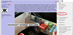
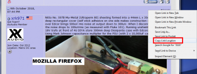
Hi 6L6: the dark art of including a link to a diyAudio post, which works for ALL members, even those who view 50 posts/screen or 100 posts/screen, is challenging and obscure. But I lay claim to having grasped it, at least this once, and here you go. It is a link to post # 3110 from 09 October 2018:
Mu Metal Boxes
Notice the insulator which prevents box-on-TeaBag-Board from shorting to rear panel.
(Right click the post number in the upper right corner, open post in new tab, copy that new URL, right...?)
Almost!
The trick is NOT to open the post in a new tab.
The trick is to select a different option when you right click the post number in the upper right corner.
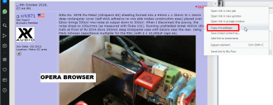
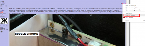
Select the option which tells your browser "Yeah, it'd be great if you'd copy this web address into the paste buffer". Four different browser examples are attached below.
Then use the contents of your paste buffer to make a link on diyAudio.
(This assumes a two button mouse with a right button that permits right clicking. For those people without a two button mouse: contemplate your life choices again.)
_
Attachments
Last edited:
- Home
- Amplifiers
- Pass Labs
- The diyAudio First Watt M2x