I bought one of your ASKA Lender preamp boards to try on the front end of the F4. I'm building an all Toshiba M2 (Got some matched Toshiba JFETS and 2SK1530/2SJ201 MOSFETS), then I'll do the F4/ASKA. Been gathering parts forever, finally got off my duff and bought a couple of 4U Chassis to get it all together (no fans, sorry).
Get soldering and try it out. You will be most pleasantly surprised.
Modification required, connect feedback resistor R10 of a dual rail Aksa Lender preamp (or Melbourne) directly to the speaker output terminal.Would it be possible to avoid the coupling cap between preamp and irfp buffer stage? Something like in the alph-m2 hybrid trad schema but keeping the mosfet bjt output stage of the preamp?
No. More explanation required. Directly connecting the Melbourne (as of presently shown) to an M2 output stage without C2 will disrupt output stage biasing and introduce DC offset at speaker output terminal.The output coupling cap on the Melbourne is optional. It is nominally 0Vdc output. Even with Edcor bypassed, you could even couple directly to the output stage without C2.
what I mean is to integrate it without any coupling cap like you did in one version of the alph-m2
https://www.diyaudio.com/forums/att...lph-m2-amp-alph-m2-schematic-dual-rail-v3-png
but keeping the mosfet mu follower / BJT preamp output stage.
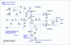
a bit like the in the fetzilla amp:
https://www.diyaudio.com/forums/att...lph-m2-amp-alph-m2-schematic-dual-rail-v3-png
but keeping the mosfet mu follower / BJT preamp output stage.
a bit like the in the fetzilla amp:
Attachments
Modification required, connect feedback resistor R10 of a dual rail Aksa Lender preamp (or Melbourne) directly to the speaker output terminal.
Yes in this case we have global feedback including the output buffer stage in the loop...
this may lead to a different sound than having local feedback to the preamp only!?
I have a couple of quick questions.
xrk971 posted a pic and description of cutting the traces and bypassing the Edcor for the Melbourne. Does anyone happen to know where the post is, I can't find it, and I'd like to incorporate a switch or something before I assemble things.
Also, does anyone have a favorite front panel power button? I want something on the large side, self latching, and in nickel or stainless.
Thanks,
-Josh
Yes, but that is the simplest modification I can think of to keep you out of trouble....Yes in this case we have global feedback including the output buffer stage in the loop... this may lead to a different sound than having local feedback to the preamp only!?
I have a couple of quick questions.
xrk971 posted a pic and description of cutting the traces and bypassing the Edcor for the Melbourne. Does anyone happen to know where the post is, I can't find it, and I'd like to incorporate a switch or something before I assemble things.
Also, does anyone have a favorite front panel power button? I want something on the large side, self latching, and in nickel or stainless.
Thanks,
-Josh
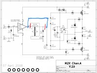
The white board is the Teabag M2 and different from Mark Johnson’s M2X. My experiment is described here:
https://www.diyaudio.com/forums/sol...pass-hybrid-m2-alph-m2-amp-3.html#post5604098
If you want to do the same bypass the Edcor trick to the M2X, here is what I would do (and you could add a DPST toggle switch to keep or bypass). Cut where red marks are and jumper where blue is. On the Teabag M2, I also cut the trace from the input terminal block to the input stage (JFETs). But since M2X has swappable input stages, you want to leave that alone.
One more thing, with the Melbourne, you can leave out the output coupling caps on the Melbourne and even bypass C2 for a DC coupled drive from the front end to the output stage. The Melbourne is designed to have close to 0mV output DC offset.
With this setup, there is only local feedback on the input stage. The output has no global feedback and this has a nice sound.
In the ALPH-M2 thread I am designing an integrated Aksa Lender front end into the amp and will use a low level global feedback from the outputs into the Aksa Lender front end. It will have much lower distortion but preserve the Aksa Lender (and Melbourne’s) dominant second harmonic and lower third harmonic distortion profile.
You might try Ali for power switches. They have a lot and they look nice too. Descriptions often mistakenly says that a on/off push button latching switch as “momentary”.
For example:
25mm flat round power mark press Button Metal brass Push Button Switch momentary 1NO press button screw terminal 25DY.F.L-in Switches from Lights & Lighting on Aliexpress.com | Alibaba Group
12mm High Round Waterproof Momentary Stainless Steel Metal Push Button Power Switch LED Light Shine Car Horn 3V 5V 12V 24V-in Switches from Lights & Lighting on Aliexpress.com | Alibaba Group
Attachments
Last edited:
No. The side of C2 connected to the opto is at ~ -4V, not 0V. If feedback is not taken from speaker output terminal, connecting Melboune bypassing C2 will disrupt output stage biasing and introduce DC offset at speaker output terminal. Please verify.... One more thing, with the Melbourne, you can leave out the output coupling caps on the Melbourne and even bypass C2 for a DC coupled drive from the front end to the output stage. The Melbourne is designed to have close to 0mV output DC offset. ...
You are right, my mistake. On the ALPH-M2, I was able to make the output offset by about -5v (adjustable) and thus, was able to bypass the C2 cap. It would take some tweaking on the Melbourne DC setpoints to get it to have a -5v DC output. Not worth it so let’s keep C2. If one wants DC coupled then just go wth ALPH-M2.
I hope that the ALPH-M2 V3 or maybe a V4 with the mosfet mu follower / bjt buffer stage (same as Melbourne ) will have same performance as the Melbourne card
https://www.diyaudio.com/forums/att...lph-m2-amp-alph-m2-schematic-dual-rail-v3-png
https://www.diyaudio.com/forums/att...lph-m2-amp-alph-m2-schematic-dual-rail-v3-png
Last edited:
I hope that the ALPH-M2 V3 or maybe a V4 with the mosfet mu follower / bjt buffer stage (same as Melbourne ) will have same performance as the Melbourne card
https://www.diyaudio.com/forums/att...lph-m2-amp-alph-m2-schematic-dual-rail-v3-png
Latest sims of V4 here and they look very decent. Using bootstrap caps on output MOSFETs, separate rail voltages for input stage. We have a 39Wrms capable amp with 27v rails.
Simulations here:
https://www.diyaudio.com/forums/sol...ass-hybrid-m2-alph-m2-amp-10.html#post5616853
Here is 8Vpp into 8ohms at 1kHz:
And here is 22.6Vpp into 8ohms at 1kHz:
Running the M2x main amplifier board from ±27 volt power supplies, will prevent owners from using all of their existing daughter cards that are designed to the First Watt M2 power supply spec: dual 18VAC secondaries + bridges + CRC filtering, giving ±23 volt supplies.
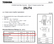
One of the daughter cards users cannot connect to a ±27 volt M2x, is "Ishikawa", thanks to the limitations of its Toshiba JFETs. Datasheet below. I assume you'll issue a complete list of approved and disapproved daughter cards for ±27 volt operation.
_
One of the daughter cards users cannot connect to a ±27 volt M2x, is "Ishikawa", thanks to the limitations of its Toshiba JFETs. Datasheet below. I assume you'll issue a complete list of approved and disapproved daughter cards for ±27 volt operation.
_
Attachments
While it is a danger, the Toshiba parts are conservatively rated. 6l6's build guide used 24 + 24 volt transformer (I did as well) which results in 30-31volt rails. Mine has run for years with no problems. This is, obviously over the advised limits. Seems like I have read somewhere on this forum they burn as 40 volts is approached, way past safety zone....I have NO idea if the L.S. versions from the store are this robust...I have only used Toshiba to 31 volts.Running the M2x main amplifier board from ±27 volt power supplies, will prevent owners from using all of their existing daughter cards that are designed to the First Watt M2 power supply spec: dual 18VAC secondaries + bridges + CRC filtering, giving ±23 volt supplies.
One of the daughter cards users cannot connect to a ±27 volt M2x, is "Ishikawa", thanks to the limitations of its Toshiba JFETs. Datasheet below. I assume you'll issue a complete list of approved and disapproved daughter cards for ±27 volt operation.
_
Russellc
You don't mean his build guide for the M2x, do you? That guide is only a few months old.
No, sorry I didn't say which amp! This was his build guide for the BA3 amplifier.
Sorry, but same Jfets....Toshiba. Have not done this with the L.S. Jfets.
Russellc
M2X Amp Main Board: Notes for Builders
2. Jumpers. When you look at the amplifier main board, you’ll see four white U‐ shaped markings inside the rectangle where the input stage module is bolted. Look for the text “I/O 1” , “I/O 2” , “I/O 3” , “I/O 4”. The U‐shaped markings are less than 1cm from those pieces of text. Just bend some scrap AWG22 wire into a U shape (resistor cut‐off leads are perfectly fine too), stuff into the component side, add a piece of masking tape to hold it in place while soldering, and solder both ends on the back. Trim flush, remove tape, done. The purpose of these jumpers is to provide a safety backup, and a backup‐to‐the‐backup, guaranteeing that the bolts are electrically connected to both sides of the amplifier main board. Even if the plated‐through‐holes somehow become no_longer_plated on this board. Yes we are preparing for a very unlikely tornado‐during‐earthquake event. But the cost of preparation is zero, so: why not?
So why do none of the pictures (which I examined) include this jumper connection? Is this a simple oversight, or was it a decision for some other reason.
Thanks for any clarifications...
- Home
- Amplifiers
- Pass Labs
- The diyAudio First Watt M2x