Hi Mark Johnson,
Does the M2X DB have access to signal GND? I only see 4 pins (Vcc, Vee, Vin, Vout). But perhaps there is a common GND somewhere?
What do you see on the schematics? Are they ambiguous? Or, are they clear and obvious and impossible to misunderstand? (post #1 in this thread contains schematics)
The Melbourne M2X Daughter-board
With Mark Johnson's OK for this project, JPS64 and I are working on an Aksa Lender DB for the M2X amp, and hopefully, it will fit in the usual 40mm x 35mm outline and compliant with the standard interface bolts. I suspect it may require a mezzanine CRCRC PSU board to clean up the rails since it is a SE Class A design with poor PSRR. Being that the design for the Aksa Lender is by Hugh Dean, the name "Melbourne" seems appropriate. A big thanks to Hugh Dean for providing the original topology and inspiration for this preamp front end.
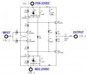
I revised the single rail schematic for dual +/-24v supplies. This input stage will require a flying lead connection #5 to the M2X's signal GND lead (somewhere on the M2X, TBD).
Here is the schematic, now revised for 0mV DC offset at the output - thus the output caps are optional and may be bypassed with a jumper:
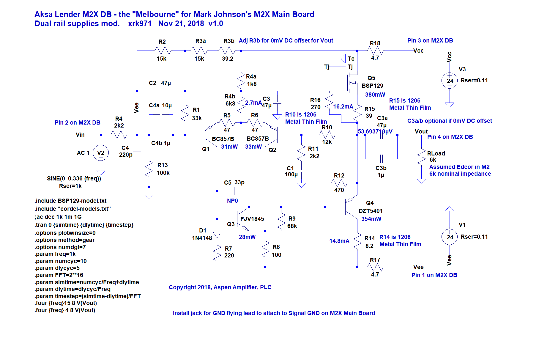
Here is predicted FFT for 4vpp into a 6k load (label on plot says 2vpp and is incorrect, someone correct me if I have assumed incorrect load impedance presented by Edcor):

The predicted distortion components are quite low for 2vpp into 6k with THD around 0.0004% and all of it as second harmonic:
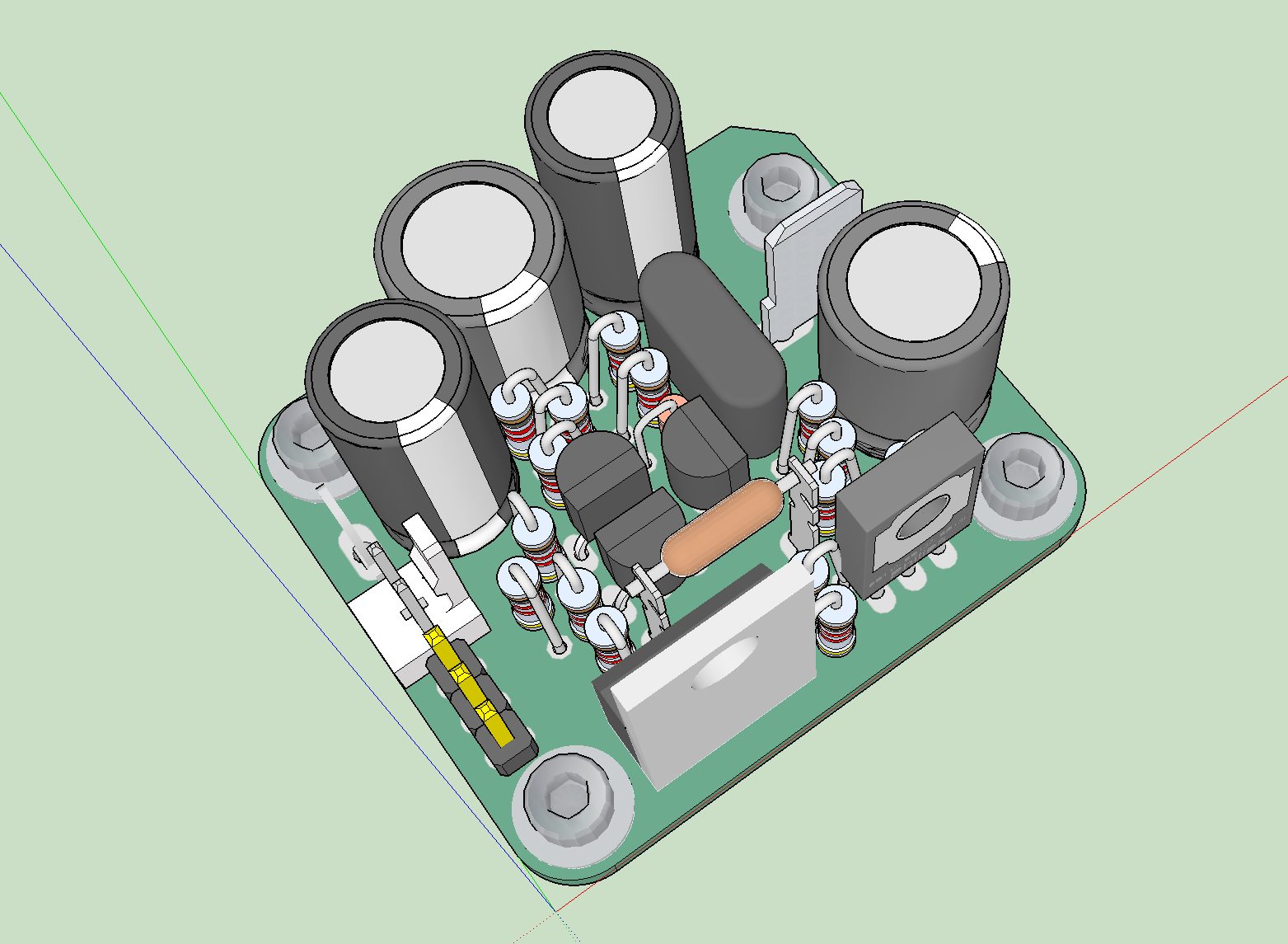
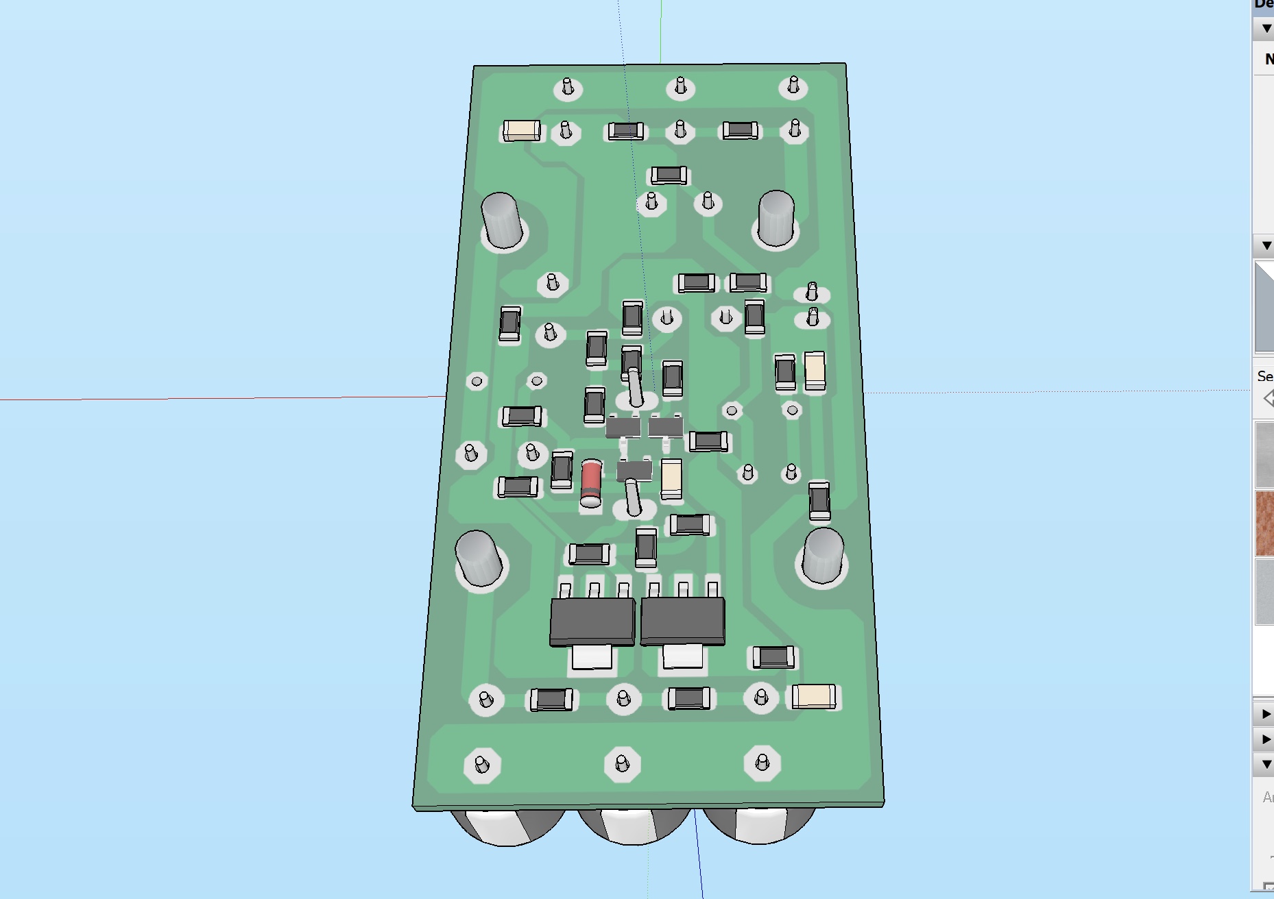
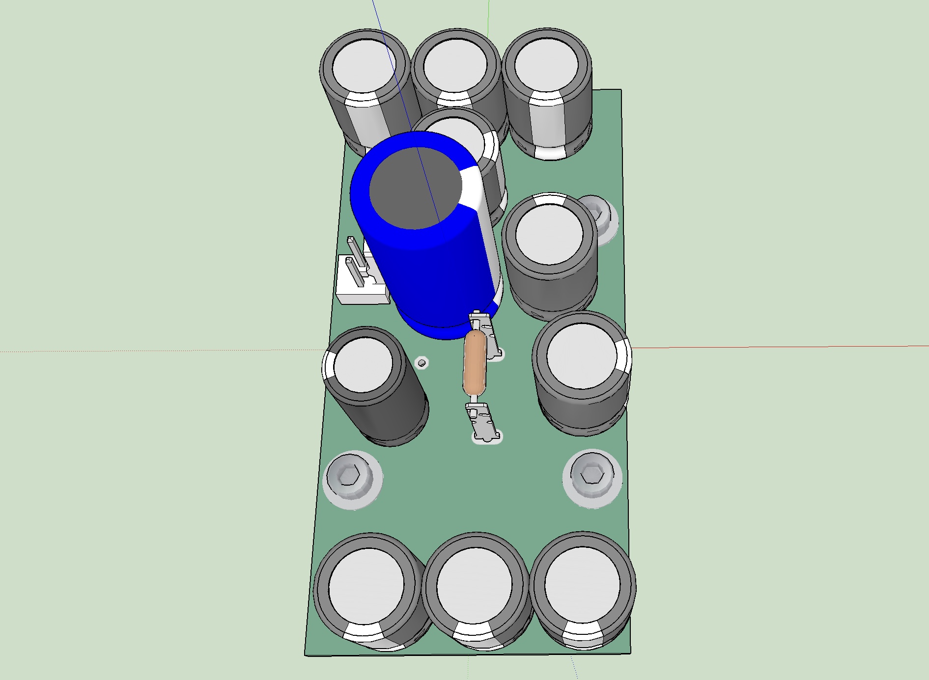
Here is an initial 3d render of the TH version of this board, although I think an SMT version using 0805 and 1206 chip resistors with SOT23 and SOT223 might be much easier to make as I hate assembling stand-up axial leads. But if the TH version is possible, we will go with that as most folks seem to prefer it for assembly.
A mezzanine board can be made with qnty 6x 470uF 35v (10mm dia x 20mm tall 5mm pitch) caps and 10R resistors. It will take the typical 12mV ripple seen on these types of Class A PSU rails and reduce to under 0.5mV ripple.
One final thought, simply changing the feedback resistors to achieve circa 26dB to 29dB gain and bypassing the Edcor, one can also check to see what the M2 sounds like without the signature of the autoformer.
With Mark Johnson's OK for this project, JPS64 and I are working on an Aksa Lender DB for the M2X amp, and hopefully, it will fit in the usual 40mm x 35mm outline and compliant with the standard interface bolts. I suspect it may require a mezzanine CRCRC PSU board to clean up the rails since it is a SE Class A design with poor PSRR. Being that the design for the Aksa Lender is by Hugh Dean, the name "Melbourne" seems appropriate. A big thanks to Hugh Dean for providing the original topology and inspiration for this preamp front end.
I revised the single rail schematic for dual +/-24v supplies. This input stage will require a flying lead connection #5 to the M2X's signal GND lead (somewhere on the M2X, TBD).
Here is the schematic, now revised for 0mV DC offset at the output - thus the output caps are optional and may be bypassed with a jumper:
Here is predicted FFT for 4vpp into a 6k load (label on plot says 2vpp and is incorrect, someone correct me if I have assumed incorrect load impedance presented by Edcor):
The predicted distortion components are quite low for 2vpp into 6k with THD around 0.0004% and all of it as second harmonic:
Code:
2vpp, 6k load
Harmonic	Frequency	 Fourier 	Normalized	 Phase  	Normalized
 Number 	  [Hz]   	Component	 Component	[degree]	Phase [deg]
    1   	1.000e+03	1.924e+00	1.000e+00	   -0.15°	    0.00°
    2   	2.000e+03	6.907e-06	3.590e-06	 -124.44°	 -124.29°
    3   	3.000e+03	1.945e-06	1.011e-06	  179.25°	  179.40°
    4   	4.000e+03	1.568e-06	8.148e-07	 -179.94°	 -179.79°
    5   	5.000e+03	1.254e-06	6.517e-07	 -179.99°	 -179.84°
    6   	6.000e+03	1.045e-06	5.431e-07	 -179.99°	 -179.84°
    7   	7.000e+03	8.958e-07	4.655e-07	 -179.99°	 -179.84°
    8   	8.000e+03	7.838e-07	4.073e-07	 -179.99°	 -179.84°
    9   	9.000e+03	6.967e-07	3.621e-07	 -179.99°	 -179.85°
   10   	1.000e+04	6.270e-07	3.259e-07	 -179.99°	 -179.85°
   11   	1.100e+04	5.700e-07	2.962e-07	 -179.99°	 -179.85°
   12   	1.200e+04	5.225e-07	2.716e-07	 -180.00°	 -179.85°
   13   	1.300e+04	4.823e-07	2.507e-07	 -180.00°	 -179.85°
   14   	1.400e+04	4.479e-07	2.328e-07	 -180.00°	 -179.85°
   15   	1.500e+04	4.180e-07	2.172e-07	 -180.00°	 -179.85°
Total Harmonic Distortion: 0.000403%(0.003347%)
Here is an initial 3d render of the TH version of this board, although I think an SMT version using 0805 and 1206 chip resistors with SOT23 and SOT223 might be much easier to make as I hate assembling stand-up axial leads. But if the TH version is possible, we will go with that as most folks seem to prefer it for assembly.
A mezzanine board can be made with qnty 6x 470uF 35v (10mm dia x 20mm tall 5mm pitch) caps and 10R resistors. It will take the typical 12mV ripple seen on these types of Class A PSU rails and reduce to under 0.5mV ripple.
One final thought, simply changing the feedback resistors to achieve circa 26dB to 29dB gain and bypassing the Edcor, one can also check to see what the M2 sounds like without the signature of the autoformer.
Attachments

Last edited:
If you can help me with a maximum extents outline relative to original, that would be helpful as I do not have an M2X in hand.they can be quite a bit larger in some directions as long as the mounting holes align.
X,
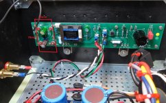
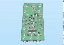
If you look at the first two pics in post # 2 of this thread, you can see the R&L main boards very well and their DB connections. Scroll down in the same post and you will see an assembled board mounted to a heatsink. That mounting looks to be what I would consider typical, and would allow easily an inch or more in the vertical (extending outward from 1-2 and 3-4) and horizontally outward from pins 2-3. You can't go horizontally in the direction of 1-4 because of the potentiometer and autoformer.
You could conceivably go much farther out, but there will be no structural support beyond the 4 mounting pins unless you expect folks to use additional mounting hardware.
Though probably a non-issue for most folks, a DB oversized by much more than a few mm may require that the main board be mounted to the heatsink before the DB is attached unless you provide cutouts for the main board hardware.
If you would like particular measurements, let me know. My boards are unstuffed at this point and I can easily measure anything you like. As well, I could scan them in "mounting position" so you can see just where things line up.
Tsmith1315,
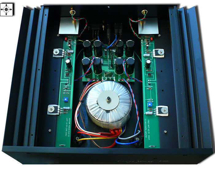
Thanks, I see that this photo indeed shows it mounted in what looks like a 4U x 300mm UMS heatsink case. There is plenty of room and perhaps all I need is another 15mm on top and bottom edges for overall 35mm x 70mm to fit everything. The dimension that goes towards the end away from Edcor is possible too but would mean DB has to be installed after main board in installed. Let me think about it.
Something like this:
Attachments
Last edited:
Mark Johnson informed me impedance of Edcor in M2 is actually closer 600ohms, so here are sims with 600ohm load for 4Vpp - nothing in circuit changed. The bias current could be increase to allow driving impedances as low as 32ohm headphones if needed.
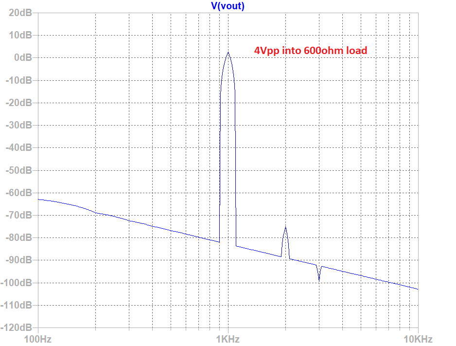
Predicted components:
Predicted components:
Code:
Harmonic	Frequency	 Fourier 	Normalized	 Phase  	Normalized
 Number 	  [Hz]   	Component	 Component	[degree]	Phase [deg]
    1   	1.000e+03	1.913e+00	1.000e+00	    0.13°	    0.00°
    2   	2.000e+03	2.494e-04	1.304e-04	  102.02°	  101.88°
    3   	3.000e+03	1.402e-05	7.328e-06	  179.41°	  179.28°
    4   	4.000e+03	2.448e-05	1.279e-05	 -176.41°	 -176.55°
    5   	5.000e+03	1.969e-05	1.029e-05	 -179.93°	 -180.06°
    6   	6.000e+03	1.630e-05	8.519e-06	 -179.98°	 -180.12°
    7   	7.000e+03	1.397e-05	7.301e-06	 -179.95°	 -180.09°
    8   	8.000e+03	1.222e-05	6.389e-06	 -179.96°	 -180.09°
    9   	9.000e+03	1.086e-05	5.679e-06	 -179.96°	 -180.10°
   10   	1.000e+04	9.778e-06	5.111e-06	 -179.97°	 -180.10°
   11   	1.100e+04	8.889e-06	4.647e-06	 -179.97°	 -180.10°
   12   	1.200e+04	8.149e-06	4.259e-06	 -179.97°	 -180.11°
   13   	1.300e+04	7.522e-06	3.932e-06	 -179.97°	 -180.11°
   14   	1.400e+04	6.985e-06	3.651e-06	 -179.98°	 -180.11°
   15   	1.500e+04	6.519e-06	3.408e-06	 -179.98°	 -180.11°
Total Harmonic Distortion: 0.013278%(0.053681%)Melbourne seems interesting indeed! Thanks for the hard work.
If I may make a strong suggestion, please do not extend the daughter board past the edge of the main board on the mosfet edge. Doing so will prevent the option of mounting the board horizontally (like the original M2).
If I may make a strong suggestion, please do not extend the daughter board past the edge of the main board on the mosfet edge. Doing so will prevent the option of mounting the board horizontally (like the original M2).
You mean like the Pass Labs M2? I don’t really see anyone using a UMS compliant board for these types of sinks? Will let JPS64 decide that as it may be to hard to shift overhang all to one end.
Also, note that overhang would be above main board, and would actually fit in this case. The Edcor transformer even is extended a bit.
Also, note that overhang would be above main board, and would actually fit in this case. The Edcor transformer even is extended a bit.
Last edited:
You mean like the Pass Labs M2? I don’t really see anyone using a UMS compliant board for these types of sinks? Will let JPS64 decide that as it may be to hard to shift overhang all to one end.
Also, note that overhang would be above main board, and would actually fit in this case. The Edcor transformer even is extended a bit.
The board can still be mounted horizontally to the DIYAudio heat sinks, it will just require a frame to be fabricated to support it. Not much effort for those of us with a shop full of tools.
There are good reasons for doing this. What most appeals to me is being able to reach the underside of the board with out removing it, and not having to put my hand deep into the case to adjust the trimmers. It will also allow the use of a shorter case since the torroid can be mounted horizontally, giving more flexibility to heatsinking for folks considering water cooling or fans.
Also, the channel B board has R5 and R10 pretty close, and an oversized daughter board will have trouble clearing them if 1/4W parts were chosen (taller standoffs will fix of course).
Given the design of the main board, the only "safe" direction to expand is off the side opposite the power transistors. I expect one could overhang it 20mm or so easily.
Or you the customer(s) could request MelbourneA1 with aspect ratio X1 by Y1, MelbourneB2 with aspect ratio X2 by Y2, and MelbourneC3 with aspect ratio X3 by Y3.
You could also take a close look at the 3D rendering in post #924 and observe that it shows six (!) off-board connectors. A 3 pin header, a 2 pin Molex, and a 1 pin 0.25" FastOn blade connector. With this many wire-to-board connections you no longer need electrical connectivity through the mounting bolts, so those could become nylon M3 bolts instead of stainless steel or zinc. Insulating bolts and hardware might give additional flexibility when mounting in, uh, novel orientations.
You could also take a close look at the 3D rendering in post #924 and observe that it shows six (!) off-board connectors. A 3 pin header, a 2 pin Molex, and a 1 pin 0.25" FastOn blade connector. With this many wire-to-board connections you no longer need electrical connectivity through the mounting bolts, so those could become nylon M3 bolts instead of stainless steel or zinc. Insulating bolts and hardware might give additional flexibility when mounting in, uh, novel orientations.
Hi Mark,
We are now trying to use the standoffs as intended - as the principal 4 connections and we have to add just one signal GND via small JST (2 pin but both the same) connector. One could choose to solder flying leads to the JST pads of course.
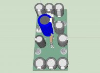
Here is an initial 3D render of the layout - sorry but JPS64 did this before we got the request for offsetting it just to the side opposite of the MOSFETs. Would this require two different DBs due to symmetry or same offset towards pins 3 and 4 isnok for both channels? First version is SMt plus through hole electrolytic caps.
We are now trying to use the standoffs as intended - as the principal 4 connections and we have to add just one signal GND via small JST (2 pin but both the same) connector. One could choose to solder flying leads to the JST pads of course.
Here is an initial 3D render of the layout - sorry but JPS64 did this before we got the request for offsetting it just to the side opposite of the MOSFETs. Would this require two different DBs due to symmetry or same offset towards pins 3 and 4 isnok for both channels? First version is SMt plus through hole electrolytic caps.
Attachments
Or you the customer(s) could request MelbourneA1 with aspect ratio X1 by Y1, MelbourneB2 with aspect ratio X2 by Y2, and MelbourneC3 with aspect ratio X3 by Y3.
You could also take a close look at the 3D rendering in post #924 and observe that it shows six (!) off-board connectors. A 3 pin header, a 2 pin Molex, and a 1 pin 0.25" FastOn blade connector. With this many wire-to-board connections you no longer need electrical connectivity through the mounting bolts, so those could become nylon M3 bolts instead of stainless steel or zinc. Insulating bolts and hardware might give additional flexibility when mounting in, uh, novel orientations.
Are you being snide? It can be difficult to tell in a forum post at times.
The Melbourne DB has only existed as a theory for hours on this thread. When else should suggestions be made? I made a simple suggestion, in what I though was a respectful manner, for a design consideration. If the suggestion is not workable or not wanted, then no problem.
I might also add to my suggestion that if the boards are horizontal, one is far less likely to drop the fasteners when swapping boards. All things considered, I feel this is a quite valid design consideration, and not deserving of being mocked.
All that said, I do like the concept behind the latest rendering, I think that a single board using SMD and TO is better than an extra layer of headers/boards.
I think your idea of improved accessibility to the underside of boards is a great one, along with your observations of lessened chances of dropping fasteners and so forth. No doubt, a wholly valid idea, that said most/many here are using chassis from the DiyAudio store and those heat sinks really don't allow for this as is.
I suppose, two solutions would be, one, as Mark says, possible differing layouts and formats for the boards which would solve, but as OP notes, it appears there may be plenty of room for mounting as is, TBD.
Secondly, maybe some sort of "conversion" brackets for sinks like Vfet uses?
Very new thread with great possibilities, looking forward to seeing this develope. Looks like I'm going to need a couple more chassis!
Oh, one question, do you have a source for heat sinks like the ones you show (Pass Labs) with horizontal mounting? Existing store chassis with pre drilled mounting layouts is likely the most popular route...wish I could source those Pass Labs style sinks!
Russellc
- Home
- Amplifiers
- Pass Labs
- The diyAudio First Watt M2x