@KevinHeem I (think I) have a setup similar to what @TungstenAudio mentions, and I can detect no hum.
I have the AKSA-Lender preamplifier feeding my M2X.
In the M2X, the Antek toroid transformer is mounted at the front (axis perpendicular to base), and the subsequent power supply hardware proceeds toward the rear. I have the Universal Power Supply board (https://diyaudiostore.com/collections/circuit-boards/products/universal-psu), without the diode part. I use a pair of diode bridges instead.
Starting from the rear of the amp moving to the front:
Hope this helps diagnose the issue.
Kind regards,
Drew
I have the AKSA-Lender preamplifier feeding my M2X.
In the M2X, the Antek toroid transformer is mounted at the front (axis perpendicular to base), and the subsequent power supply hardware proceeds toward the rear. I have the Universal Power Supply board (https://diyaudiostore.com/collections/circuit-boards/products/universal-psu), without the diode part. I use a pair of diode bridges instead.
Starting from the rear of the amp moving to the front:
- Shaefter mains connector with integrated fuse holder and noise circuitry.
- Power wire to a TV-3 type switch (ALPS SDL1P), with a 1uF film capacitor in parallel.
- Power & neutral connecting wires to a terminal block near the front. These are probably the longest wires in the power path.
- CL-60 thermistor on power line. (This will be replaced with a slow-start ckt)
- Transformer primaries
- Transformer secondaries
- Diode bridges
- Power supply CRC board
- Finally, at the back, V+/V- pairs of connecting wires, mounted along the base, following the sides of the chassis closely, to each channel of the M2X motherboards.
Hope this helps diagnose the issue.
Kind regards,
Drew
@KevinHeem , all that to say that for me shielding the AC wires from the mains connector to the terminal block is not necessary.
Perhaps in your case you could mount the power supply board on longer standoffs, and so move it away from the AC wires, if those turn out to be the culprit.
Kind regards,
Drew
Perhaps in your case you could mount the power supply board on longer standoffs, and so move it away from the AC wires, if those turn out to be the culprit.
Kind regards,
Drew
The power transformer probably radiates much more EMI than the two AC mains wires. Having the power transformer at the back right next to the low level audio signal wires and audio input jacks may inject noise into the audio signal. So moving the transformer to the front and flipping the audio PCBs so that the signal transformers are the back may be the best arrangement.
Also twist all wires with their returns. That will reduce the amount of EMI that they may pick up and also reduce the amount of EMI that they may radiate. When there are three wires in a group, it is better to twist them together than to braid them. A tight twist of three wires has a smaller loop area than a tight braid.
https://www.diyaudio.com/community/threads/3-wire-power-twist-or-braid.313999/

As I think about it, the main reason I originally built using this "a** backwards" configuration is that years ago I used to play with the Halfler DH-200 series of amps. Those amps were so susceptible to hum from the power cord, which ran from the power inlet in back to the switch up front, and also snaked near the "input" board. Just moving this AC wire around slightly in the Halfler made a huge difference in hum at the output of the amp. While my current configuration for FW amps worked okay with the F5, F4, M2, Aleph J, all those had the small signal inputs near the center of the boards. Now with the M2x board being designed with the inputs near one end, in the "backwards" configuration this creates a huge antenna running from the RCA's in back to the board input connections near the front.@KevinHeem , all that to say that for me shielding the AC wires from the mains connector to the terminal block is not necessary.
I'll try running the AC wire in this "new" configuration of this chassis without any shielding and see what happens...
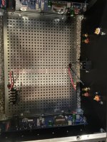
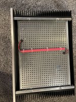
I am no expert but this is how I ran my mains wiring. Back from IEC to transformer mounted at front plate. Wiring twisted tightly and run thru a piece of poly tubing wrapped in faraday tape then red shrink tube underside of bottom plate. Plenty of room for improvement on some other wiring but with MU covers on input transformers this is very quiet. Need to actually measure/validate & fine tune wiring. Critiques welcomed.
Attachments
Solved M2X hum issue. Read tons among many threads iteratively did these (1) moved output ground from amp PCBs to PS (2) lead dress improvements by minimizing purple transformer shield ground, high voltage PS leads, IED inlet ground. Moved one bridge rectifier away from the other. Slight rotation of Antek 4128, aiming leads as far away from boards as possible. Already had the Antek heavy steel shield installed, and it's vertical, to the front with the leads front facing. Input transformers remain unshielded. Checked twist jobs on the wiring, and yes, the three wire sections were not braided, properly done initially per Ben's post.
Listening closely to small sensitive test speakers informed one channel buzzier than the other. Leading down the pathway to re-examine the Universal Power Supply schematic.
Aha! PS ground from one 'side' of the PS PCB, singular through NTC to avoid ground loops spurred question: what's the pathway then for the other half of the PS board, the noisier channel?
Turns out I had omitted a jumper that then necessitated the ground path to travel counterclockwise back up to the input of the PS PCB. Corrected, now a very quiet amp.
https://www.diyaudio.com/community/...cuit-board-v3-illustrated-build-guide.244788/
Image here from the build guide so you can see the omission:
Good evening,
I wanted to thank Mark Johnson and others for the build guide and of course Mr Pass! I just completed the amp on Sunday and have been listening to the mountain view, so far it’s an extremely enjoyable sonic experience. I have built the other cards, but I will spend a week or two with each, but it will be challenging to convince myself to switch the Mt View out. I also appreciate the builders that had challenges, I learned a ton from just reading the post. What a great community of builders!
Than you for all you do!
Kelly,
Attachments
I'm Finally aboard the M2X Train!
Thanks to all of you that issued my ticket!. Nelson Pass, Mark Johnson, 6L6, ZM(just because ya cant thank him enough), and the rest of the community that taught me so much.
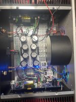
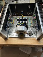
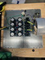
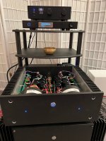
This build received a bunch of parts that I had collected over the past several decades and decided that none of us were getting any younger and should go into this project. Chassis from group buy of 20 years ago, the Toshiba mosfets 2sk1430/2sj201 that i purchased from Blues, the power supply boards from Tea and the Sumr donuts from group buy from years ago. A few new touches are the LT4320 rectifiers with Prasi's boards. Mark's H9KPXG soft start and front switch is a such a nice "touch".
Thanks to those that worked out the values to get the Toshiba mosfets to work with the opticoupler, EUVL, ZM, Chede, Addidub. R11=0 and R13 and R14 to 0R33. I measure get 1.76A on left channel and 1.73A on right. My rails with load are at 26.5V. ( so a little higher than usual first watt). Temp of top of chassis with thermocouple is 45C. Feels more like Blimey plus hot. Hand can make 6-7 sec. offset adjusted to within a mV.
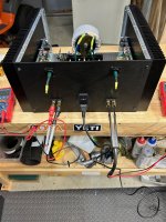
Was concerned about the possibility of hum. Opted for dual mono as "better" and also less potential for ground loops. Was concerned that two big donuts might be a problem for the Edcor but build was silent at my speakers. Although the mains were 86 dB the test speakers that are higher efficiency were also silent. Nevertheless every Edcor deserves a nice mu metal hat
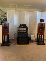
I'm setting the baseline listening with the Ishikawa's . Have the Mountain View, Tucson and Milpitas completed and have the parts and boards for Norwood, Austin and IPS7. I think I'll take my time with each rather than rushing to what seems to be peoples favorites.
The M2X is sitting the the shoulders of the Sissysit monoblocks. It will take a heavy lift (literally and figuratively) to move the Sissysits out of first place. Although not a competition more like a well stocked (wine) amp cellar. Recently completed Iron Pre added the "sweetness" that system needed. Love the muses volume control.
I plan on testing with REW. What I would like to determine is if the toshiba mosfets had much of an effect on the phase of H2. I know that EUVL has mentioned very small variations of the degeneration Resistors as having impact as well as ZM tailoring many of his offerings for H2 phase. Would be nice to know how much (if any dif) in sound is due to the different mosfets vs the subtle changes in H2 amount and phase. For that matter would be nice to know what happens to H2 and its phase with each of the daughter cards.
For know will just enjoy the music! Thanks again for the gift of your generosity!
Jack
Thanks to all of you that issued my ticket!. Nelson Pass, Mark Johnson, 6L6, ZM(just because ya cant thank him enough), and the rest of the community that taught me so much.
This build received a bunch of parts that I had collected over the past several decades and decided that none of us were getting any younger and should go into this project. Chassis from group buy of 20 years ago, the Toshiba mosfets 2sk1430/2sj201 that i purchased from Blues, the power supply boards from Tea and the Sumr donuts from group buy from years ago. A few new touches are the LT4320 rectifiers with Prasi's boards. Mark's H9KPXG soft start and front switch is a such a nice "touch".
Thanks to those that worked out the values to get the Toshiba mosfets to work with the opticoupler, EUVL, ZM, Chede, Addidub. R11=0 and R13 and R14 to 0R33. I measure get 1.76A on left channel and 1.73A on right. My rails with load are at 26.5V. ( so a little higher than usual first watt). Temp of top of chassis with thermocouple is 45C. Feels more like Blimey plus hot. Hand can make 6-7 sec. offset adjusted to within a mV.
Was concerned about the possibility of hum. Opted for dual mono as "better" and also less potential for ground loops. Was concerned that two big donuts might be a problem for the Edcor but build was silent at my speakers. Although the mains were 86 dB the test speakers that are higher efficiency were also silent. Nevertheless every Edcor deserves a nice mu metal hat
I'm setting the baseline listening with the Ishikawa's . Have the Mountain View, Tucson and Milpitas completed and have the parts and boards for Norwood, Austin and IPS7. I think I'll take my time with each rather than rushing to what seems to be peoples favorites.
The M2X is sitting the the shoulders of the Sissysit monoblocks. It will take a heavy lift (literally and figuratively) to move the Sissysits out of first place. Although not a competition more like a well stocked (wine) amp cellar. Recently completed Iron Pre added the "sweetness" that system needed. Love the muses volume control.
I plan on testing with REW. What I would like to determine is if the toshiba mosfets had much of an effect on the phase of H2. I know that EUVL has mentioned very small variations of the degeneration Resistors as having impact as well as ZM tailoring many of his offerings for H2 phase. Would be nice to know how much (if any dif) in sound is due to the different mosfets vs the subtle changes in H2 amount and phase. For that matter would be nice to know what happens to H2 and its phase with each of the daughter cards.
For know will just enjoy the music! Thanks again for the gift of your generosity!
Jack
Attachments
-
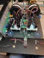 Cap banks grounding and board connection.jpg1.1 MB · Views: 52
 -
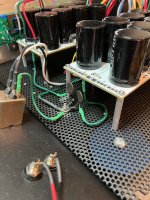 ground close up.jpg947.8 KB · Views: 51
 -
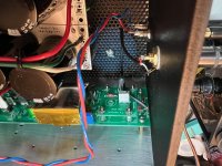 Ishikawa board connection and mu metal box.jpg672.4 KB · Views: 53
 -
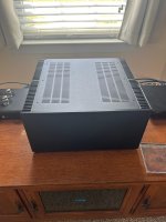
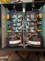 M2X top view complete.jpg1 MB · Views: 53
 -
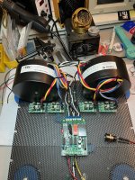 Transformers LT4320 and soft start.jpg1.2 MB · Views: 54
 -
 amp stack.jpg1,002.5 KB · Views: 56
 -
 M2X w Iron Pre.jpg486.4 KB · Views: 58
- Home
- Amplifiers
- Pass Labs
- The diyAudio First Watt M2x