And it saves you from having to learn the color code. Or, worse, having to decide whether the third band on this tiny resistor, is red or orange or brown.
Oh, and if you happen to have some LEDs made of clear plastic, so it's impossible to know what color they are, the cheapo Mega328 tester actually lights them up while it measures Vfwd and while it decides which pin is the cathode. So you get a visual confirmation: this one glows green!
_
Oh, and if you happen to have some LEDs made of clear plastic, so it's impossible to know what color they are, the cheapo Mega328 tester actually lights them up while it measures Vfwd and while it decides which pin is the cathode. So you get a visual confirmation: this one glows green!
_
Last edited:
the $13 part tester that Mark recommends everywhere
Do you have a link please?
Do you have a link please?
Google or Amazon - “Mega328 tester” and you will have numerous options.
Do you have a link please?
Sure:
https://www.amazon.com/gp/product/B07WT9VVZB/ref=ppx_od_dt_b_asin_title_s00?ie=UTF8&psc=1
This one comes with a nice acrylic case to protect the device.
Hi all I'm beginning a build. I've searched for a good while and I'm having a hard time finding the spade / blade connecters used here and in other threads. Mark Johnson mentions them in post #3 and #131, but I can't find what he's talking about on Mouser or otherwise. He says they're available to buy in bulk in long strips that you clip off.
Can anyone point me to the PCB mounted space connectors we are using here, and the associated female crimp-on connectors?
Thanks folks.
Can anyone point me to the PCB mounted space connectors we are using here, and the associated female crimp-on connectors?
Thanks folks.
I recently ordered these:
62409-1 TE Connectivity | Mouser
Individual parts, no need to cut them apart.
62409-1 TE Connectivity | Mouser
Individual parts, no need to cut them apart.
I recently ordered these:
62409-1 TE Connectivity | Mouser
Individual parts, no need to cut them apart.
Thanks a bundle for the help. If I understand correctly, these would be an appropriate female terminal to use with the spades. Similarly Faston 250 series and specc'd for 14AWG. Am I correct?
170032-4 TE Connectivity / AMP | Mouser
(Edited to a version I can buy in singles)
Last edited:
Can anyone point me to the PCB mounted space connectors we are using here, and the
associated female crimp-on connectors?
Whichever parts you order, be sure to get the mating parts from the same mfr that are
intended to be used together. Mixing brands can cause poor fit, looseness, and unreliability.
Can anyone point me to the PCB mounted spade/blade connectors we are using here, and the associated female crimp-on connectors?
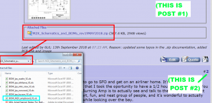
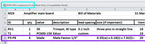
The M2x package sold by the diyAudio Store includes twelve PCBs. Each PCB has an associated "BOM" (Bill Of Materials), which is attached to post #1 of the M2x thread. Example part numbers at Mouser.com are provided for most components in the BOM, including these FastOn blade (male) connectors. Images attached below.
_
Attachments
")
Yes its positive!Hello Ake,
nice to hear/read that!
I hope the Black Forest Buffer was a positive surprise....
Cheers
Dirk
Part of this build includes me learning how to navigate Mouser and Digitech.
…and learning their names as well 😂
Good tips, Rafa!
Thanks, Rafa! I hadn't thought of ensuring component values are visible (couldn't see the forest for the trees in that debugging thread). Color bands can be indistinct (as Mark noted) but we could see them in any orientation.
I will definitely add that to my Definition of Done for this and future builds
Kind regards,
Drew
Well, I think there are great lessons to learn from Craig’s adventure:
- double checking values is never a wasted time
- ensuring letters of values on resistors are facing upwards is not just for “aesthetics” (or ensuring color bands all match the same orientation)
- when requesting measurements it would be ideal to post pictures of the ACTUAL moment of measurement
- it helps to keep the basic rules of series and parallel components at hand. 220k in series with 100R would, indeed just show as, basically, 220K.
...
Rafa.
Thanks, Rafa! I hadn't thought of ensuring component values are visible (couldn't see the forest for the trees in that debugging thread). Color bands can be indistinct (as Mark noted) but we could see them in any orientation.
I will definitely add that to my Definition of Done for this and future builds
Kind regards,
Drew
All the suggestions are valid and follow good practices for success. One practice that needs to be discussed is the use of an auto-ranging DMM to check values. IMHO this is where the problem arose. A 221 ohm resister shows 221 on the display and a 221K ohm resistor shows 221 on the display. On my auto-ranging meter the k does not appear as the next value in the display after 221 and is near the lower corner of the display window. It could be missed depending on the viewing angle. And expectation can play at part here. If you are expecting 221 and you see 221 it would be easy to miss the small k or if you are expecting 321 and you see 221 again easy to miss the k.
Just what I learned from all of this.
Just what I learned from all of this.
I reckon yet another thing to learn from that story is - if you see some misterious things happening and start suspecting issues like bad batch of PCBs from diyStore, mislabled resistors from Mouser or something even more gruesome, - pause, make 3 steps back and look into the mirror - "*we* are the gremlins", as ZM once said...
- Home
- Amplifiers
- Pass Labs
- The diyAudio First Watt M2x