Ok then its okay then,that was the thing I had allready mounted the board to the hetasink.you will see that the traces are already connected between those points.
I se this small squared solder pads under the IPS with a symbol that they should be soldered together?
However, if an impatient builder is in a big hurry to power-on their M2x boards, and if they decide to skip this simple step (which saves ten minutes), then in my opinion, they are taking on unnecessary risk. Avoidable risk.
In any case, we should remind ourselves: the "Y" in "DIY" identifies the final decisionmaker. It's your money, it's your board, you are free to practice your hobby in whatever way pleases you the most.
Might as well solder them,as you say it takes 10 minutes..In any case, we should remind ourselves: the "Y" in "DIY" identifies the final decisionmaker. It's your money, it's your board, you are free to practice your hobby in whatever way pleases you the most.
When I´d bolted the mainboards to the heatsinks I se this small squared solder pads under the IPS with a symbol that they should be soldered together?
Should they?
Do you have a link to a source for those connectors for the daughter board? I'm planning on building at least 5 of the input stages and they look like a real time saver.
Security Check
Security Check
But they seems out of stock,could it have sommething to do with M2x....???
Don´t know why it says security check,the links are working.
Security Check
But they seems out of stock,could it have sommething to do with M2x....???
Don´t know why it says security check,the links are working.
Last edited:
When I´d bolted the mainboards to the heatsinks I se this small squared solder pads under the IPS with a symbol that they should be soldered together?
Should they?
Thanks. Shipping costs of 32 Euro to the US will probably stop me from getting those and I haven't found a similar part on Mouser.Security Check
Security Check
But they seems out of stock,could it have sommething to do with M2x....???
Don´t know why it says security check,the links are working.
Looking for guidance on my Power supply for my “in process” M2x.
Previous class A I used 40kuF per channel, like the build guide suggests as a minimum. And it sounds great, no issues.
Question: I have planned to used 60kuF in this M2x per channel, but have come across some large 100kuF “can style” caps and could use 100kuF per channel.
Any real sound benefits I would get going with 100kuF vs. 60kuF for each channel - all else being equal (same 400VA 2x18Vac transformer and 35A1000V rectifiers in both)
One thing to consider is that the Edcor signal transformer is susceptible to picking up external EM fields. Steel cases for the power transformers will help mitigate this, as will a copper shield around the Edcor. Some have also found Mu metal boxes that fit around the Edcor.
Any real sound benefits I would get going with 100kuF vs. 60kuF for each channel - all else being equal (same 400VA 2x18Vac transformer and 35A1000V rectifiers in both)
Benefit? Probably not. Will still work nicely though…
One thing to consider is that the Edcor signal transformer is susceptible to picking up external EM fields. Steel cases for the power transformers will help mitigate this, as will a copper shield around the Edcor. Some have also found Mu metal boxes that fit around the Edcor.
I have all of the above on my M2X and it is absolutely silent. The downside is that I now wonder if doing all that was necessary.

I have all of the above on my M2X and it is absolutely silent. The downside is that I now wonder if doing all that was necessary.
I will let you know because I don’t plan on any of it. But it won’t be the first time I go back and revise a build afterwards.
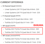
I notice the store has 2 jfet mA ranges (8 to 11 mA and 6 to 8 mA)for the quads needed for this amp. Which is the correct one for the ishikawa input boards? Or will either work?
Here's the Matched JFET page from the diyAudio Store as of today. Either one of the two options in the red box, will work very nicely in the Ishikawa input stage boards.
_
Attachments
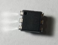
The Vishay 4N35 I bought for the M2X Q5 optoisolator doesn't have a notch or any markings for pin numbers except for a single dot on the top of the package. The datasheet doesn't appear to include any relevant information for this packaging about the pinouts. I assume the dot is pin 1 but can anybody confirm that?
Thanks.
Paul
Thanks.
Paul
Attachments
- Home
- Amplifiers
- Pass Labs
- The diyAudio First Watt M2x