That makes sense. If my DMM is connected to speaker terminals and I turn on power, as output slowly rises to about 150mV, that’s when hum starts. Output will then settle back down as things warm up to about 20mV, but hum continues. I have an Antek 4218 I had considered using that I might swap in to see if it makes a difference. I still think I need to account for the different readings at R13 and R14 on the left and right boards. That can’t be right. I think the recommended numbers have been posted but I can’t find them now.
I also switched transformers to some "super-duper" audio grade expensive transformers and it may have reduced the hum a bit but the transformers was not the "root cause" of the hum. It was DC-introduced in the transformer and this is cause by asymmetri at primary and/or secondary side of transformer.
Regarding asymmetry, my primaries are equal and my secondaries measure the same, but I do have unequal DC output. My negative voltage out is about 1.5 volts higher than positive. But that’s after going through the diodes and CRC filter. (I used the full Universal PSU board with stock components.) Or could that disparity be the symptom of something causing hum?
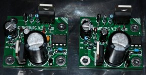
Oh, and I found the recommended voltage range across R13 and 14. NP himself says between 560 mV and 750 mV is expected. Again, mine is 650 and 650 on one board, but 510 and 790 on the other. So I’d still like to run down the reason for the difference.
Oh, and I found the recommended voltage range across R13 and 14. NP himself says between 560 mV and 750 mV is expected. Again, mine is 650 and 650 on one board, but 510 and 790 on the other. So I’d still like to run down the reason for the difference.
Last edited:
1.5V in difference between positiv and negativ DC rail is a lot as the current draw from both rails should be equal.
Also the bias current through R13 and R14 is the same and as they have same value voltage drop should be about the same. But as they are 5% resistors if one is 5% on the high side and the other is 5% on the low side there will be a difference but more than 200 mV difference as you see is strange.
Is that with no speaker connected and DC-offset only a few mV?
There must be a "current leak" somewhere......
About the asymmetry.....if you have same AC out of both secondary......check just after bridge......just after the first set of capatitors.....just after the R in the CRC and so on to see where you see the difference showing up.
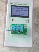
I got this tester:Since this is now all working, here are the Gerber files as promised.
This version is slightly revised to give more space between components for soldering.
Circuit remains unchanged.
Happy soldering,
Patrick
.
Can it be used to match the 2SK209GR?
Attachments
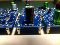
Finally made this upgrade...systemic issues with loosening bolts over time...I do tend to board swap however. Also possible I didn't follow 6L6 washer formula to the letter.
Worthwhile upgrade—I sleep better at night now.... in spite of the fact that I could make Cedarburg permanent and be totally happy.
Parts: male, female
@pfarrell, thanks a lot for the inspiration and the links to the best source for the D-SUB contacts! I also went this way yesterday and am absolutely happy about this. My willingness to change the buffer cards is absolutelly different now!
Attachments
Patrick/EUVL or Dirk/cubicincher
Re: Black Forest Buffer
There seem to be discrepancies between the revised BOM (post 4923) and the PDF version (post 4920) of the schematic.
Regarding components Rs1 and Rs2, is the value 300 ohms as it shows in the schematic? The Mouser TWW5J30RE points to a 30 ohm resistor, not 300 ohm. I assume the schematic should read 30 ohms for Rs1 and Rs2.
On the schematic, component labeled Rs5 should be labeled Rs12 I think.
Best,
Anand.
@pfarrell, thanks a lot for the inspiration and the links to the best source for the D-SUB contacts! I also went this way yesterday and am absolutely happy about this. My willingness to change the buffer cards is absolutelly different now!
avitkauskas,
could you kindly share which exact type you ended up buying ?
That looks very neat !
Thanks,
Max
I keep making silly mistakes these days.
My apologies.
> Regarding components Rs1 and Rs2, is the value 300 ohms as it shows in the schematic?
Yes, 300R. And should be TWM5J300E.
You need the resistor to drop 12V at 40mA.
> On the schematic, component labeled Rs5 should be labeled Rs12 I think.
Also correct.
Silly mistake because LTSpice does the numbering for you automatically.
And if you forget to manually correct them, you get mistakes like this.
Here both revised files in Zip.
Patrick
.
Attachments
And it seems that the Ohmite 300R 5W is currently not in stock.
So you can replace them with 2x 2W 150R metal oxide, e.g. Panasonic ERG-2SJ151.
See example :
https://www.diyaudio.com/forums/att...4d1617720666-diyaudio-watt-m2x-210406-bfb-jpg
Patrick
So you can replace them with 2x 2W 150R metal oxide, e.g. Panasonic ERG-2SJ151.
See example :
https://www.diyaudio.com/forums/att...4d1617720666-diyaudio-watt-m2x-210406-bfb-jpg
Patrick
> I have tried 330 Ohm, 300 Ohm and 270 Ohm.
> With 270 Ohm I've got closest to the 12 V railvoltage.
That depends somewhat on your rail voltage.
And I assume they are symmetrical (nominally +/-24V).
The buffer itself consumes 33mA nominal.
The circuit around the power LED will set the voltage across the buffer to 24V.
That means that Rs1,2 both have to drop 12V, to get from +/-24V to +/-12V.
With a 300R resistor, the required current to drop 12V is 40mA.
33mA for the buffer, 7mA for the LED / Qs1.
With 330R, current becomes 36mA. So 3mA for the LED.
With 270R, current is 44mA. LED needs to take 11mA.
The LED / Qs1 is designed such that they will take the entire 40mA.
But then you should not work them unnecessarily hard.
7mA is already very bright.
If your buffer bias is much more than 30mA (+/-3mA), you should change the value of R11,12.
Reducing from 300R will reduce bias.
The numbers given in the excel sheet is for guidance only.
The exact value depends on your 2SK209 JFETs.
So I advise you order a couple of different values around the nominal, after your JFET matching.
Patrick
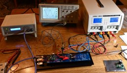
In building the BFB, I suggest you start with the buffer alone and leave out all the regulator parts (with suffix s).
You have better access to compoments, and can use a +/-12V lab supply with 40mA current limit to power up.
You do need the caps Cs1,2.
Once this is proven to work, the rest can go on afterwards.
Very little that can go wrong.
And you need some heat sinking for the power transistors.
Patrick
You have better access to compoments, and can use a +/-12V lab supply with 40mA current limit to power up.
You do need the caps Cs1,2.
Once this is proven to work, the rest can go on afterwards.
Very little that can go wrong.
And you need some heat sinking for the power transistors.
Patrick
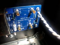
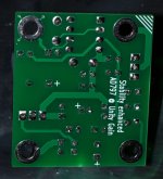
I now have a set of Cedarburg AD797 boards ready for testing. Boards are also cleaned for flux
What I wondered after the build is that this input board has no coupling cap at the output like Norwood, Tucson, IPS7 and other boards has.
Is the simple reason for this that there was no space on the board for the non-polar 220uF cap? ......so we need to be "fearless" and just hope Edcor survives?
What I wondered after the build is that this input board has no coupling cap at the output like Norwood, Tucson, IPS7 and other boards has.
Is the simple reason for this that there was no space on the board for the non-polar 220uF cap? ......so we need to be "fearless" and just hope Edcor survives?
Attachments
- Home
- Amplifiers
- Pass Labs
- The diyAudio First Watt M2x