 Thank you for sharing the photos!
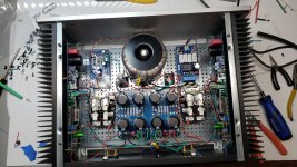
Here's my M2X in a chassis I built around some surplus heatsinks I found online. The PSU boards are my own design - I prefer screw terminals, and I needed a longer aspect ratio to fit into this chassis. I also wanted extra terminals before and after the pi resistors for attaching a CapMX if I wanted to substitute one for the pi resistors (for a future design).
I am running 0.39R source resistors to up the bias a bit, because I have more than enough heatsink for it. Internal air temp is 110 deg. F / 43 deg. C. The heatsinks themselves are warm, but I can leave my hands on them indefinitely without any discomfort.
I built up the Tucson first to get it playing, and then I soldered up the Norwood for fun this afternoon - first time to use SMD.
Derived from first principles of diyaudio and spectacular!

that in fig 3 is for a split supply from std supply. How does that apply to the unity gain buffer in fig 12??
A split supply is nothing more than a unity gain buffer.
If you must, just use 1k/15k, and calculate C as in the data sheet.
The gain of the M2 is given by gain of 2x source follower (~1) x gain of transformer.
The latter is given by the transformer turn ratio for AC signal, not ?
Cheers,
Patrick
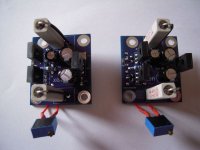
a little appetizer -for a new M2X-input board from EUVL
but still under test - too early to tell something....
EUVL / Patricks design!
I am only soldering a little bit...
Oh, yes! The boards are not cleaned yet....
Greets
Dirk
but still under test - too early to tell something....
EUVL / Patricks design!
I am only soldering a little bit...
Oh, yes! The boards are not cleaned yet....
Greets
Dirk
Attachments
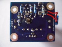
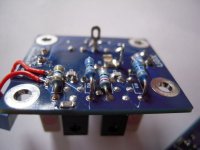
1) Those ceramic power resistors are only temporary. Will be replaced by much nicer prettier ones to come.
2) The trimmers are there to set the DC offset. Will be replaced by fixed resistors later.
3) An output coupling cap is included in the Alpha version. It can be bypassed with a jumper later.
There is a Vbe-multiplier on board which acts as a shunt regulator to provide local +/-12V for the buffer.
Both the buffer and the regulator have been tested on breadboard.
The output DC is stable and can be easily trimmed.
So I do not expect the coupling cap to be needed in the end.
Unless you like the added sound of the coupling caps.
Patrick
As promised Spice file for the BFB for 48V rails, including on-board shunt regulator.
Patrick
.
2sk209GR or Y ok instead of the obsolete 117?
Just finished wiring it up. Set offset to 0 volts and measured 0.65 volts across the source resistors. Need to load test it.
what are all those additional electromechanical looking components and boards for?
any teaser of the active components? only BJT?
no unobtainium parts?
The diyAudio First Watt M2x
Patrick
I think you'll discover that member @marconi118 is not yet ready to build input stage cards today, and probably won't be ready for several more months. When the time eventually does come, he will lay out PCBs himself, and probably won't choose to make them compatible with the M2x removable daughter card physical interface.
When the so-called "Front End card" interface for the Nelson Pass VFET amplifier is released ("coming soon!" is Mr. Pass's most recent statement), I expect many DIYers who create their own PCBs will probably copy that newer physical interface instead of the older M2x interface. (So they'd also need to re-layout the M2x amplifier board). I can't reveal what the new interface IS, but I can reveal it ISN'T four M3 bolts.
_
I never buy pcbs or kits, I always try to adapt to my needs liking and simplify to the max
When the so-called "Front End card" interface for the Nelson Pass VFET amplifier is released ("coming soon!" is Mr. Pass's most recent statement), I expect many DIYers who create their own PCBs will probably copy that newer physical interface instead of the older M2x interface. (So they'd also need to re-layout the M2x amplifier board). I can't reveal what the new interface IS, but I can reveal it ISN'T four M3 bolts.
_
Last edited:
When the so-called "Front End card" interface for the Nelson Pass VFET amplifier is released ("coming soon!" is Mr. Pass's most recent statement), I expect many DIYers who create their own PCBs will probably copy that newer physical interface instead of the older M2x interface. (So they'd also need to re-layout the M2x amplifier board). I can't reveal what the new interface IS, but I can reveal it ISN'T four M3 bolts.
Now you tell me! I wanted to redesign the M2x PCB for a while but you keep coming up with new cards for it so I finally gave up and soldered 4 brass bolts on the bottom PCB so I can get the cards in and out of there easy.
And picture of the BFB Alpha Test PCB.
People asked to be one of the Alpha testers.
Before you ask for PCBs, you should be capable of :
1) matching JFETs in SOT23 (Idss), and BJTs in TO126 (hfe);
2) soldering SMT devices down to 0805 / SOT23-5;
3) know how to trim DC offsets and solve oscillations problems.
If the answer to the above is all positive, you can get in touch with cubicincher.
You will have to cover the cost of 2x PCBs, plus postage to your location from Germany.
The postage fees (DHL Small packet) you can see here :
Packchen international | DHL
Cheers,
Patrick
- Home
- Amplifiers
- Pass Labs
- The diyAudio First Watt M2x