Has anybody made a small "test bench" for testing M2X input boards before they are put into work on amp board?
Hi MEPER,
That’s actually a good idea! How about this
")
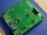
Testboard for M2x format daughter boards (Yarra Pream/M2x amplifier)
Attachments
@Meper
My speakers are 88dB effective. Yesterday, when the amplifier was turned on, I noticed that the offset increased to ~ 100mV. I adjusted but later checked the power and there was a 0.2V difference on the rails. I corrected all faston connectors and had to adjust the offset again because the voltages were equal.
Yesterday I put covers on the edcor. I used old LCD shields. Hope they help at least a little before I get mumetal. I am curious if I can check if the edcor is the source of this 250Hz noise? Is it possible to "remove" edcor from the amplifier circuit but without desoldering?
One of the test fixtures I built in Feb 2018, is displayed in post #439 of this thread.Has anybody made a small "test bench" for testing M2X input boards before they are put into work on amp board?
Notice that this Forum thread, that you're now reading, was born two months later, on April 28th, 2018.
The test fixture preceded the M2x amplifier, and the discussion thread. As is appropriate!
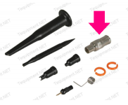
It's got BNC connectors to facilitate ultra high speed square wave testing; you really do need a low inductance ground for your scope probe, to display 2 nanosecond rise time square waves without ringing. If you're lucky, your probe came with an "accessory kit" which included a scopeprobe-to-BNC adapter like the one below. Voila, ultra low inductance connection between probe and PCB.
_
Attachments
Last edited:
@Meper
I am curious if I can check if the edcor is the source of this 250Hz noise? Is it possible to "remove" edcor from the amplifier circuit but without desoldering? View attachment 900435
I would not try to do such experiments.....to try to bypass Edcor.......if I understand you correct.
@Darrr, what a lovely nice fitting Edcor covers! Looks like being custom made for that! What kind of LCD cover is it?
Concerning your hum. How loud it actually is to your ears? Do you hear it, say, 50 cm from the speakers? From your listening position? Does it bother you while listening to the music?
I also have some small hum of 100Hz when the ear is next to the speaker (Klipsch RP-600M, ~90+ dB/W/m), but I cannot hear it in 50 cm from the speaker, so I do not care so much.
Attempting to use Instagram to post pictures
Well, it sort of works
An externally hosted image should be here but it was not working when we last tested it.
An externally hosted image should be here but it was not working when we last tested it.
Well, it sort of works
@avitkaskas
I hear it from 20-50 cm. Aplication spectroid show me ~ - 85dB at 5cm from speaker.
The 100hz noise disappeared when I removed connection from PS board to "gnd pos"
I don't know what the LCD was but it was destined for garbage. This is what it looks like.
@MEPER
Yes. I meant bypass.
I have to correct the wiring at the bridges. I have a problem on the faston connector. By moving it, the voltage drops on this rail. By the way, the question is, did I exaggerate by giving solidcore 12ga on the +/- connections with the speaker connectors?
View attachment 900447
Last edited:
If you have bad connection you need to fix this. It may be the reason why your DC-offset is not stable. It will also cause other problems.
The connector you use has to be compatible with the wire gage you use. Really thick solid core wires can be like an "elephant" in the room and maybe make some mechanical stress on e.g. connectors on a PCB. AWG 12 is probably ok but on the "heavy" side. Maybe AWG 14-16 is what most use for the short distances inside the amp for the PSU.
The connector you use has to be compatible with the wire gage you use. Really thick solid core wires can be like an "elephant" in the room and maybe make some mechanical stress on e.g. connectors on a PCB. AWG 12 is probably ok but on the "heavy" side. Maybe AWG 14-16 is what most use for the short distances inside the amp for the PSU.
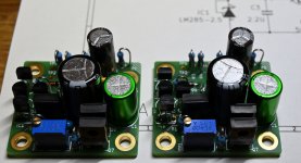
Now I got this far with IPS#6 and they are ready to be tested (test wires not yet installed). The 330 uF cap was a bit on the fat side......but fits.
If boards are tested and adjusted in a test bench using a lab power supply I guess the final adjustment should be when boards are installed in M2X.
I wonder what the reason would be to install a jumper as R5 and then bypass R4. Then conditions are changed after the adjustment.....
If I knew more about diff. amps I would probably know the answer......
Attachments
I had the same thought... here's a link that may, or may not help.
https://www.diyaudio.com/forums/pass-labs/321925-diyaudio-watt-m2x-373.html#post6388342
JT
https://www.diyaudio.com/forums/pass-labs/321925-diyaudio-watt-m2x-373.html#post6388342
JT
I think it would be strange to install the R5 jumper when the designer of the circuit did not do it. But since it is made possible it is probably because according to some "school books" the circuit should be like that......is my guess.
It could be interesting to know why some may want to install the jumper.
we may probably find out if we start reading about JFET diff amps.....
It could be interesting to know why some may want to install the jumper.
we may probably find out if we start reading about JFET diff amps.....
My take, is R4 need to be there for the adjustment, but is not needed after, but the designer left us an option to jump it after we adjust... I don't understand what's going on enough to decide one way or the other... After I adjusted, I left R5 open as did the designer.
IPS6 Controversy Seekers:
Read post #3408 and focus upon the final paragraph. Then ruminate upon the situation, draw up a list of possible actions, form your own expert opinion, and then act upon it. There are plenty of people who read this thread at least once a week, who definitely WILL install jumper resistor R5=0 after setting the trimpot. I have not done that, on any of the IPS6 boards that I built. So far anyway. It's your call. I've made my call.
_
Last edited:
It is probably because of Q1 current generator. If both JFETs are matched and current adjusted to 0V then both JFETs are biased to same current (about 3 mA) and then there is no need for R4 anymore. We will know that resistors will introduce a bit of noise and some may see it as an improvement to remove (bypass) a resistor that is not needed anymore?
It's a binary option, very few experiments are required to completely explore all possibilities. An example protocol having no un-soldering at all, might be
Easy!
- Build the IPS6 boards and omit the R5 jumpers
- Install the IPS6 boards into M2x and listen for a few weeks, until you are well familiar with their sound.
- Remove the IPS6 boards and solder in the R5 jumpers. Reinstall them into the M2x and listen to this version for another few weeks.
- Decide whether you liked the "without R5 jumper" sound, or the "with R5 jumper" sound.
- If you prefer the "without" option, just cut the wire. You don't even need to renove the daughterboards from the amplifier. You don't need to un-solder anything
Easy!
I am sure in a A/B blind test I would not be able to hear a difference. I don't even think I would be able to measure a difference. I like the idea better that I can check the two test points over time if boards are still "calibrated" to 0V (without the need to cut anything).
I improved the wiring. Now I have no problems with loose connectors. The noise has decreased and its frequency has changed. According to spectroid it is 150 and 200hz. What else can I do?
In the second pic , a screenshot from the oscilloscope with the inputs shorted and the outputs open

In the second pic , a screenshot from the oscilloscope with the inputs shorted and the outputs open
- Home
- Amplifiers
- Pass Labs
- The diyAudio First Watt M2x