There must be something I am missing, I don't have a simulator and I am not an expert in circuit topology BUT but as I recall NP claims the input capacitance is claimed to be a few pf. At the same time the input fets in question are 30pf input capacitance. Clearly the circuit at unity gain must be doing some cancellation.
Can someone clarify?
Can someone clarify?
Might be a good idea to wait a week or so, to give @grataku adequate time to check the earlier thread, and see if this has been asked and answered by The Actual Circuit Designer Of Ishikawa himself.
Official M2 schematic
Official M2 schematic
Might be a good idea to wait a week or so, to give @grataku adequate time to check the earlier thread, and see if this has been asked and answered by The Actual Circuit Designer Of Ishikawa himself.
Official M2 schematic
What can I say, that's a gold mine.

Now browsing page 337...
Last edited:
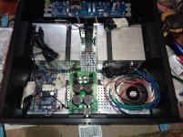
New M2X Monos coming along...
These will be active cooled through the case sideways. Two fan one blowing in and one blowing out straight through the sinks. They should run pretty cool. Input run is about 2 inches and the output about 3.5. The scut on the front is just tape adhesive. I taped it all off when I machined it.
These will be active cooled through the case sideways. Two fan one blowing in and one blowing out straight through the sinks. They should run pretty cool.
Input run is about 2 inches and the output about 3.5. The scut on the front is just tape adhesive. I taped it all off when I machined it.Attachments
Last edited:
Nice! What brand of transformer is that? It looks close to what I just bought.
Antek
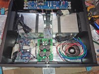
I lighten the shadows, so you can see the fans. We'll see how they do, I have something to use for shrouds if needed... It's got a temp sensor build into the blocks that hold the chip to the sink. Also, reused the stock mounting from the computer processor, just the springs holding it in place. There was plenty of force to keep them in place.
Attachments
Last edited:
Antek
I lighten the shadows, so you can see the fans. We'll see how they do, I have something to use for shrouds if needed... It's got a temp sensor build into the blocks that hold the chip to the sink. Also, reused the stock mounting from the computer processor, just the springs holding it in place. There was plenty of force to keep them in place.
The M2X channel board has become almost incidental to the mono block.
Don
Antek
Yep, that's what I got. 200VA 2x18v. I figured whatever. Draw is 160w plus some other loss. I always oversized the trafo in the past, for some dubious deeper base reproduction myth...in the first Watt LOL
Too many quaranteened diyers Antec is fresh out of 300VAs.
Maybe you plan for it already but I would put something between the heatsinks to create a tunnel and get a push-pull fan action. You could slow those fans to a gentle breeze.
Last edited:
Maybe you plan for it already but I would put something between the heatsinks to create a tunnel and get a push-pull fan action. You could slow those fans to a gentle breeze.
Yes, I think I said so earlier, but I do have a shroud option waiting if needed.
Basically, some flexible flame retard weather stripping.
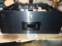
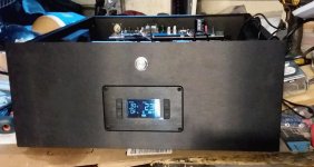
Fan panel, temp alarm auto speed
Fired the soft start and power supply, all good there.... test the M2 and then build a daughter... witch one first?!
Here's what I am using...
Amazon.com: AC Infinity AIRPLATE T8 PRO, Quiet Cooling Dual-Fan System 6" with Thermostat Control, for Home Theater AV Cabinets: Home Improvement
Fired the soft start and power supply, all good there.... test the M2 and then build a daughter... witch one first?!
Here's what I am using...
Amazon.com: AC Infinity AIRPLATE T8 PRO, Quiet Cooling Dual-Fan System 6" with Thermostat Control, for Home Theater AV Cabinets: Home Improvement
Attachments
This looks like an implementation of LATB's approach with the Mac G5 heat sinks. It appears you are going to run one channel's devices per heat sink.
I have a question on the lead length allowable between those output devices and the amplifier board- when one uses a single heat sink per board, invariably, the lead length from the device's legs to the board now moves to several inches, requiring lead extensions.
My question is, does this additional lead length incur any undesirable side effects, or require specific attention to how this is done, or, are the electrical properties of the device unimpeded by a few inches of lead back to the board?
Mark? Tungsten? Anyone?
I suppose a critical listen to the final arrangement would tell the story, but I kind of hate to embark on a 'success oriented expectation' of the build, as the building up and taking down is kind of a PITA.
This looks like an implementation of LATB's approach with the Mac G5 heat sinks. It appears you are going to run one channel's devices per heat sink.
I have a question on the lead length allowable between those output devices and the amplifier board- when one uses a single heat sink per board, invariably, the lead length from the device's legs to the board now moves to several inches, requiring lead extensions.
My question is, does this additional lead length incur any undesirable side effects, or require specific attention to how this is done, or, are the electrical properties of the device unimpeded by a few inches of lead back to the board?
Mark? Tungsten? Anyone?
I suppose a critical listen to the final arrangement would tell the story, but I kind of hate to embark on a 'success oriented expectation' of the build, as the building up and taking down is kind of a PITA.
Tom, so far we are good so far DC offset is .003 mV GDS all look good. the Alpha Nirvana uses flying leads and has no issues, however that is not the same design.
By the way, it's up and running and the sinks are running 30-31C after an hour. lol I guess the shrouds won't be needed.
The leads are about 3 inches and standard 16ga hookup wire. I do happen to be listening to another M2x that bolts directly to the sinks, so I should be able to run some tests down the line, but I dare say that there won't be an issue.
BTW IT"S ALIVE! Haven't built the daughter yet, but everything looks great... have to do the honey do list today, so I can't do a board.
I still have to build the other mono too, but that should be much easier now that I know where the snags are.I can tell you I'm sold on the active cooling as long as it doesn.t have any unintended results on the sound.... Saturated at about 30C, but that's with the fans on high... next stop drop them down to low. They are not silent, but good enough for my purpose.
Last edited:
Congratulations, very nice!
I hope we'll hear from the experts about the cable extensions -- I moved the gate stoppers and also the source/output resistors out directly to the MOSFETs. For the gate stoppers I'm assuming there is an RC-thing going on with the internal gate capacitance and adding additional L through longer leads might cause instabilities? Would be great if somebody could explain this better! Anyway, e.g. XRK even put snubbers on his external MOSFET helper boards (see here).
By also moving the source resistors I could reduce the number of connections necessary. I'm actually just connecting the MOSFET assembly, with the gate stoppers and source resistors, directly to the power supply (which is in a separate housing). So there are four leads going between there and the PSU, V+, V-, Output, Ground -- fits nicely on one SpeakON connector per channel. Then I connect the speakers directly to the PSU box.
This is actually pretty cool: I have my beefy double-mono PSU and my M2X, F6, and soon also AJ output stages just plug in there -- can switch between them in seconds. Nice! In case anyone is interested, I can show a diagram and a couple of pictures.
I really agree with you on being sold on active cooling!
Regarding air flow: From my thermal measurements, the thermal resistance between the MOSFETs and the cooling leads is pretty high, and diverting some air to the MOSFET area directly can bring down the operating temperature by maybe 15 degC. But then, it probably does not matter as one can easily keep the temp on top of the MOSFETs below 55 degree. For you, with one of your >~100Watt coolers per MOSFET this is very generously dimensioned (I'm running both MOSFETs per channel on one cooler, which works fine, too).
BTW, I gave up on PWM temperature regulation for the moment. It *does* introduce some (quite low) additional noise level into the system, I think through the fan cables, despite complete electrical separation. Also, at least in my case, it is just not needed. I bought a "fancy" 120mm fan (NF-S12B redux-700, ~$14). That one can just run, it's completely silent.
I'm looking forward to hear about your listening tests.
I've never built an M2 or an M2x with fly-wires between the PCB and the output MOSFETs; I have always, without exception, soldered the MOSFET leads straight into the PCB with no intervening wires or cables or conductive doo-dads of any kind. I imagine if you asked Nelson Pass whether he has ever built an M2 with the output transistors not soldered directly to the PCB, the answer would probably be no.
Personally I am not enthusiastic about the idea; it offers too many opportunities to create unwanted ("parasitic") inductance and capacitance elements, which, according to Murphy's Law, increase (not decrease) the likelihood of unwanted oscillation. I myself would be more likely to mount the store PCB + MOSFETs on a 10mm thick aluminum plate, and then bond the super-finned, super-wind-tunnel, super-cooler to the back side of the plate -- if I wanted to dissipate significantly, enormously more than 30W in each MOSFET, which I do not.
But you are not me and vice versa; feel free to try any experiment you like, and enjoy both the results and the journey. Just don't try to duck the responsibility of ownership. It's your idea, you are responsible for its success or failure. You are responsible for any fires it starts or house wiring it destroys.
Likewise, I have always soldered the Mosfets of my various diy amps directly to the PCBs. The M2 (& M2x) is relatively modest for power consumption, and generally doesn't need heroic measures such as forced air cooling.
Having said that, there are a few who have built amps with flying leads to the output devices to overcome various chassis / heatsink configurations, usually at higher power levels per device. The MoFo is one example where this is a fairly common occurrence. I will eventually be using flying leads to connect to the big SIT hockey pucks in a couple amps that are waiting for PCBs to be available.
The trick is to keep the wires as short as reasonably possible, and to re-locate the gate stopper resistor so it is close or directly connected to the Gate pin of the transistor. If one is using PCBs with locations for gate stoppers, those will need to be jumpered, or wired in a way to make proper connection to the output drivers.
Thanks for the input so far... as for, "heroic measures," that isn't the case at all. I wanted to put them in a smaller case and by far, the largest cost is the case and sinks. The sink for these was 12 and if I went with a couple fans and no PMW, that would be another $20 or so. This means even if I was to cool something like an F5T V3, I would not need those massive passive sinks and the huge case that houses them. The next build will, most likely be something 100-150W per channel and active cooling could save hundreds in such a case. I wanted to try the idea on something more forgiving and get my mind around it.
You could use Xs mosfet helper boards like on the AN, I mentioned it to him in a PM, but never heard back on it.
LATB, hell ya, show me what you moved and where... I was wondering about oscillation as well.
You could use Xs mosfet helper boards like on the AN, I mentioned it to him in a PM, but never heard back on it.
LATB, hell ya, show me what you moved and where... I was wondering about oscillation as well.
Last edited:
- Home
- Amplifiers
- Pass Labs
- The diyAudio First Watt M2x