I did?
I thought so, didn't you, "Bum," a ride from Mark and discuss this on the way from something or other?

You may assist the control of the bottom end by adding 12,000 uF to 24,000 uF to the outputs of the SLB boards.
What sort of frequencies are you considering the "bottom end"? I posted some simulations here that show a moderate drop in output impedance above 100hz when 22mF is added to the output of the Gtose CapMx. Based on the sims, I'm going to have equal capacitance before and after a CapMx in my PSU. Could this contribute to the effect you observe/hear?
The internal caps you have before the CFP are fine. I’m recommending added caps on the output of each CFP.
Brother, remember you are talking to a board stuffer, and at this point a stuffer with a couple of Irish whiskeys in him.
I barely know CFP= what.. Complimentary Feedback Pair? Are you talking about where C21 and C22 are now? Feel free to explain to me like I'm a 8yr old.

Preferably with pictures hahah.
Attachments
Yes CFP = Complementary Feedback Pair
The easiest way to add the extra caps would be to use screw terminal can types connected to the extra V+, GND and V- spade lugs on the output of the SLB boards. Or you could use snap in terminal caps wired directly to the SLB boards. Leave the 220 uF caps at C21 and C22 in place. The big caps end up in parallel with these.
The easiest way to add the extra caps would be to use screw terminal can types connected to the extra V+, GND and V- spade lugs on the output of the SLB boards. Or you could use snap in terminal caps wired directly to the SLB boards. Leave the 220 uF caps at C21 and C22 in place. The big caps end up in parallel with these.
Yes CFP = Complementary Feedback Pair
The easiest way to add the extra caps would be to use screw terminal can types connected to the extra V+, GND and V- spade lugs on the output of the SLB boards. Or you could use snap in terminal caps wired directly to the SLB boards. Leave the 220 uF caps at C21 and C22 in place. The big caps end up in parallel with these.
Okay, do you have a preference in caps?
KEMET ALS70 series, screw terminal, 40V.
I went through this process with my F6.
Okay, on the way...
JT
@TungstenAudio / Thompsontechs and others -
I've read with interest about the use of "Motor Run" caps etc. Similarly, I'm a board stuffer trying to learn a bit more about what I've been building.
Are caps in this application similar? I have similar speakers to JT's, so we may be after some of the same characteristics. Is the basic idea to have a bit more instantly available oooomph in layperson's terms? I've seen the sizes range from what TA recommends on up to some physically massive parts. Different FW amps seem to perform very differently in terms of how I perceive the bass. If it goes back to the PSU - I'd welcome trying some changes.
JT - I can't remember, did you build the Austin boards? FWIW, they had (to my ears) a pretty nifty effect on the spatial presentation of the music.
MH,
I just built the Pass version of it.
I understand what TA is saying, I don't know the numbers, but do understand. A good analogy might be when you using air tools. If you have a small tank the motor compressor is always fighting to keep up and losing. If I have a 100 gallon tank, I can use the tool harder longer before the compressor ever kicks in. Most of the time, the load is reduced or gone by the time the compressor kicks on and it can top off under a smaller load.
I am also wondering if the AN might benefit from this as well. I have the same supply in that as well. I'm going to give this a listen and decide if it's worth another $60.
JT, that is a good analogy.
But isn’t the “compressor” constantly running in a Class A amplifier/psu? Unlike Class AB where there are high demand and low demand psu requirements that the ‘100 gallon tank’ will even out?
That's a very good question, class A is running wide open at all times, but I would submit that wide open with and without load are a different animal especially with regard to impedance's. Also with mains voltage fluctuations to be considered as well.
Anyway, thanks for making me think, I'm curious what some of the others who have more knowledge than I, have to say.
JT, that is a good analogy.
But isn’t the “compressor” constantly running in a Class A amplifier/psu?
I did a lot of reading about this question. This article by Rod Elliott is helpful: Class-A Amplifiers explained
Actually, the idea that a Class-A amp draws a continuous steady current from the supply is true in one case only. A single ended amp using a current source as the collector load will draw a continuous steady current - but only if it uses a single supply. In the case of a dual supply, the same amp will draw a continuous current from one supply, and a varying current from the other. (My thanks to Geoff Moss for pointing this out - a detail that few published designs have ever mentioned !)
An amp that uses a fixed current source of (say) 2.5A from the positive supply will draw 2.5A regardless of load or signal level, but only from the positive supply. The negative supply current will vary from 2.5A at no signal, but will be almost zero at maximum positive swing, when the lower transistor is turned off, and the current flows from the current source to the load. At maximum negative signal swing, the negative supply current will be close to double the quiescent current, since the lower transistor now carries the current from both the load and the current source.
This 'small' detail seems to have received scant reference in any of the articles I have read, but it will make a very big difference to the power supply. In this respect, I do not feel that the single ended version should be operated from a dual supply. If it is so important to you to eliminate the coupling capacitor, then I suggest that either a push-pull Class-A design be used, or build separate power supplies for each polarity.
But also
balanced push-pull Class A output stages also tend to have constant draw.
Last edited:
spice test
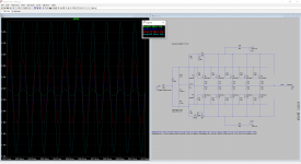
Here's a quick test with LTSpice I ran with a BA-2 output stage, which should correlate to the M2. "Ampl" is the input to the OS in volts, and the waveform is the current drawn from the positive rail. Looking at the waveform through the source resistors, it remains in class A (the FETs pass a clean sine wave without flattening).
Nelson's comment makes sense - in a balanced amplifier, the out-of-phase variations would cancel, presenting a relatively constant load.
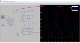
EDIT: Balanced sim added just for fun. "Ampl" is input to the front end this time. The current through the positive rail has much less variation.
Here's a quick test with LTSpice I ran with a BA-2 output stage, which should correlate to the M2. "Ampl" is the input to the OS in volts, and the waveform is the current drawn from the positive rail. Looking at the waveform through the source resistors, it remains in class A (the FETs pass a clean sine wave without flattening).
Nelson's comment makes sense - in a balanced amplifier, the out-of-phase variations would cancel, presenting a relatively constant load.
EDIT: Balanced sim added just for fun. "Ampl" is input to the front end this time. The current through the positive rail has much less variation.
Attachments
Last edited:
thompsontechs, which preamp are you using with the M2x?Oh my, first thing that hit me was the soudstage, this things is wide and deep, I'm hearing stuff from behind me lmao. Nice job Mark and Pappa. It doesn't control the bottom end like the AN, but man, this thing is just musical as hell. Dire Straits playing right now WOW!!
Regards.
thompsontechs, which preamp are you using with the M2x?
Regards.
PC-Singzer-KIT-Holo=
- Home
- Amplifiers
- Pass Labs
- The diyAudio First Watt M2x