Short answer is "yes". You need a matched pair of K170BL and J74BL grades ( the store might be O.O.S. of the matched pairs or quads however)and mount them in thermal contact with each other on the pcb, either using a small zip tie to bind them together or heat shrink them together. See post #1 of this thread.
Are the LSK 170 B grades sold in the DIYAUDIO STORE suitable for mounting «ISHIKAWA input stage V1 «in the M2X amplifier?
Yes, but you will also need LSJ74, which is not in stock atm. And better to buy together with LSK170, as you need matched pairs.
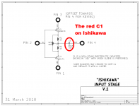
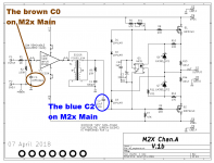
Ishikawa C2 is optional and can be replaced with a jumper. Yes, you could use a MKP as well. C2 was added in the case you want to add a coupling cap to ensure that there is zero DC on the core of the signal transformer. The original M2 schematic did not have a capacitor there, so omitting C2 and replacing with a jumper would be closest to the original configuration.
C2 is on oryginal M2 . Optional on ishikawa is C1.Ishikawa C2 is optional and can be replaced with a jumper. Yes, you could use a MKP as well. C2 was added in the case you want to add a coupling cap to ensure that there is zero DC on the core of the signal transformer. The original M2 schematic did not have a capacitor there, so omitting C2 and replacing with a jumper would be closest to the original configuration.
My question is why can it be dc on edcore if i have matched fets?
Last edited:
Sorry, found issue, loose connection on rectifier! Now to continue listening to the Tucson card really nice .
I had similar issue. One wire from power supply not soldered!
Russellc
The transformer in my M2x is rated 300VA. It has two independent secondaries, each 18V (AC) @ 8.3 amps RMS.
My M2x uses the power supply circuit design by Nelson Pass, schematic in post #83 of this thread...... but I decided to purchase electrolytic capacitors rated for 35V (not 25V) just to have a little bit of extra safety margin.
Hi MJ, are you going to post the files or make available boards
for us mere mortals to acquire? It probably would be helpful to
many people too.
Just a thought.
Cheers,
Schematic from post #83
Suitable PCB to build that circuit - Universal Power Supply – diyAudio Store
Photo of example build using the circuit and the PCB -
And here's photo of that very same PSU in an M2x -


.
Suitable PCB to build that circuit - Universal Power Supply – diyAudio Store
Photo of example build using the circuit and the PCB -

And here's photo of that very same PSU in an M2x -

.
Last edited:
Looks good. Thanks for pointing me in the correct location
for it.
It's nice that you even got the navigation LEDs correct!

I also like international navigation standards and put
my front walk way lights using the same standard.
RED = Port; Green = Starboard
At least for Halloween.
Cheers,
for it.
It's nice that you even got the navigation LEDs correct!
I also like international navigation standards and put
my front walk way lights using the same standard.
RED = Port; Green = Starboard
At least for Halloween.
Cheers,
Hi MJ, are you going to post the files or make available boards
It's time for you to learn to create your own PCBs. The good news is, this is not especially difficult, and you don't need to be an EE with a degree to be successful. The software is free and there are three dozen PCB fabs that will build your boards at incredibly cheap prices; see pcbshopper dot com for hard data.
Here's a DIYer who had "minimal experience in electronics" yet taught himself to layout PCBs for his first-ever diyAudio project: an Amp Camp Amp. If he can do it, you can do it: post #6029, You've got much more DIY experience than him, and in Dallas you have access to resources that are every bit as good as the resources he had in Pretoria, South Africa. If he can do it, so can you.
My Gosh MJ,
That last time I tried to make a board for phono amp, it
took me a month of screwing around with it, and I eventually
said screw it.
Eagle isn't too user friendly and trying to ID
all the parts.... and on and on it went, I was
hoping it would be a bit simpler.
After a while my hands can't take the mouse and
clicking....
I should try and scrap the old file and give it a go again.
Cheers,
I also like international navigation standards and put
my front walk way lights using the same standard.
RED = Port; Green = Starboard
At least for Halloween.
Buoyage System A or B ? (Red Right Return ...)
Sorry for the Off Topic, but I couldn't resist ...
Regards, Claas
Tucson op amp adaptor
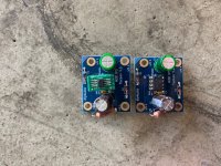
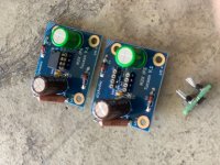
So the Tucson BOM lists two op amps, OPA604AP and OPA611. The first is a through-hole device and the second is an SMD. The Tucson daughter card allows you to use either. I wanted to try both, but was feeling particularly cheap with respect to buying two cards.Moreover, either Jim or Mark mentioned that there are many good audio op amps available as SMDs. What is a DIYer to do with so many options?
Short answer: solder tails and SMD adaptors. The images show how I used to the solder tails so as to be able to switch out op amps. I got the idea while building a Pearl2 whereby I wanted the flexibility to switch resistors and caps to vary the operation for different carts. For the Tucson SMDs I purchased an SMD adaptor and modified it. The modification, which used the thickest clipped leads i had in my e-waste bucket, was developed since the adaptor pins are WAY too large to fit in the solder tails I purchased, and I didn't want to purchase others. I used the template for aligning the pins that came with the adaptor to line up the clipped leads and voila! Now all that needs be done to try different SMD op amps is purchasing additional adaptors (cheap), and I can plug in any number of SMD op amps, or switch back to through hole varieties.
Not a great breakthrough by any stretch, but a very minor engineering application for a issue that didn't really need addressing. Fun though.
/d
Attachments
I'm using a new opamp chip in my Tucson input boards, and loving the results. It's the LT1122 by Analog Devices / Linear Technology, datasheet attached below. JFET input, 14 megahertz bandwidth, 60 volts/usec slew rate (!), through hole DIP-8 packaging, and best of all, designed and spec'd and guaranteed to drive 600 ohm loads. The Edcor transformer is a 600 ohm load, which means it's a match made in heaven.
The LT1122 is in active production, it's in stock and on the shelf at the major first-tier distributors (link)
"Opamp rollers" might really enjoy rolling out their OPA604s and rolling in some LT1122s. I sure did.
One of the DIY projects I'm bringing to Burning Amp 2019, includes LT1122s. Stop by and have a look / have a listen.
MJ
_
Attachments
- Home
- Amplifiers
- Pass Labs
- The diyAudio First Watt M2x
