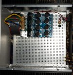
I have finished first step of PSU build for the two large Deluxe chassis and tried to minimize radiation from wires by making them as short as possible. I hope the distance from toroid to Edcor and the shielding of the toroid and Edcor will minimize noise. Now I will build 2. step of PSUs and after that mount the M2X boards. The wires of the 500 VA toroid secondary was too stiff to work with and mount into the PSU board. For external bridges it would be OK. So in theory wires could be shorter. I look forward to perform some noise measurements and see what I can learn from that when amp is op and running!
For safety I have ordered some "flex" to put around the 230 VAC wires from IEC to toroid.
For safety I have ordered some "flex" to put around the 230 VAC wires from IEC to toroid.
Attachments
I have also tested PSUs as they are now and everything works as expected. 3A was no problem which is about double as needed for one M2X board. Toroid was 100% silent. No mechanical noise which was good. Fuses could also tolerate the inrush current which was no surprise as now there are 4AT in IEC fuse holder. I have ordered 1.6T, 2.0T and 2.5T. Then we will see how well the NTC inrush limiter works. We can hope for 1.6T.
I've finished my M2X build using the SLB PSU. I've only completed the Tucson IPS so far. When powered up the heatsinks get warm and I see 0.61V across the big 0.47R 3W resistor, indicating a healthy bias current.
When the amp is driven directly from my phone's audio out there is sound from the speaker but at a low volume, which I assume is due to the limited output power of the phone. However, when I use the preamp output from a Pioneer SC-35 receiver to drive the M2X there isn't any sound out of the speakers at all (except some hum). I've tried it with optional capacitor 0 both in and out of the circuit. I've also tried substituting a different amp in for the M2X, using the preamp-out from the Pioneer, and it works as expected with good volume at the speaker. So, does anyone have any idea why the M2X wouldn't like the signal from the Pioneer?
One other thing that worries me a little: the PSU voltage is +/-25.6, making 51.2V total at the Tucson IPS. According to a comment from Mark Johnson the IPS boards are designed for 50V max.
Also, if anyone can provide more info on testing the Tucson IPS board I'd appreciate it.
How are you attaching the Pioneer to the M2x? Photos please.
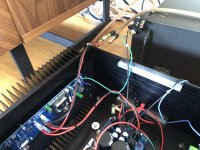
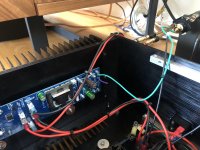
There is an RCA jack with the center conductor connected to the input at the end of the M2X board. Per xrk971 the RCA's ground (outer conductor) goes to the PSU ground.
I'll work on getting some pictures....
Here are a couple pictures. As you can see I only have one RCA input connected since I'm only testing one channel at the moment. The input and speaker jacks will be mounted in the back panel this weekend.
Attachments
Last edited:
I've finished my M2X build using the SLB PSU. I've only completed the Tucson IPS so far. When powered up the heatsinks get warm and I see 0.61V across the big 0.47R 3W resistor, indicating a healthy bias current.
When the amp is driven directly from my phone's audio out there is sound from the speaker but at a low volume, which I assume is due to the limited output power of the phone. However, when I use the preamp output from a Pioneer SC-35 receiver to drive the M2X there isn't any sound out of the speakers at all (except some hum). I've tried it with optional capacitor 0 both in and out of the circuit. I've also tried substituting a different amp in for the M2X, using the preamp-out from the Pioneer, and it works as expected with good volume at the speaker. So, does anyone have any idea why the M2X wouldn't like the signal from the Pioneer?
One other thing that worries me a little: the PSU voltage is +/-25.6, making 51.2V total at the Tucson IPS. According to a comment from Mark Johnson the IPS boards are designed for 50V max.
Also, if anyone can provide more info on testing the Tucson IPS board I'd appreciate it.
Have you checked polarity of your source relative to the amp? One time I got very weak sound it was because my source was connected to the ground of the amp and the GND of the source was connected to the +ve Input.
Good suggestion but I neglected to mention that I tried that too.
Is it possible to bypass the IPS board? Can I remove it and put a jumper between IPS input posts 2 and 4 on the M2X board?
I removed the Tucson boards and put a jumper across 2 and 4. Using my phone as a signal source the M2X now plays much louder than when the boards were in place. Finally sweet, sweet music! While I think about what could be wrong with my Tucson boards, which by the way are using OPA1611 op-amps, I may build a different IPS such as Mtn. View.
Even with the IPS boards removed and bypassed my M2X still doesn’t work with the Pioneer receiver as the signal source; I can’t get any sound out of it. The Pioneer has no problem driving my Hafler amp. It’s got me stumped…
This sounds somewhat similar to something I experienced with my M2X build. I initially used a Cary SLP-98P preamp with the M2X. It sounded great. Even though I had absolutely no good reason to do so, I decided to try a different preamp, the Audible Illusions Modulus 3A. Using the same source, audio levels were very low. To get an acceptable volume I had to increase gain way beyond where it would normally be. Even then the levels weren't great and tube noise was audible.
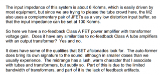
I suspect the issue was impedance matching. The Cary, at 440 ohms works well with the standard 100 Kohm load of the M2X. The Audible, at 1.2 Kohms isn't a good match. My experience has been that a 100 Kohm load on a power amp needs to see <1000 ohms from the preamp. Others may have had a different experience.
Also, you might want to test with a different source, like a CD player.


Hi Folks,
Sorry I have chimed in for a while, I have been upside down with work and projects.
I have a real mess (of my own making) that I hope you all can help me straighten out.
I completed the M2 last winter, and I have been loving it - it is an exceptional amp.
I put everything together as a prototype for the final assembly of the amplifier, and I am just now getting around to wrapping up the project. Up until now, the power supply and micro-controller boards have been done point-to-point on perf board.
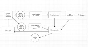
I designed boards for the power supply, DC protection, and microntroller, and had them made up by JLCPCB.
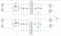
Please see the block diagram for the layout. I have also included the PS schematic (basically the same stuff we all use), a table with test results, and the official M2 schematic so folks won't have to dig it out of their files.
So here is the story:
I populated the power supply, verified I am getting +/- 25 DCV at the outputs. I installed it into the amp, and started it with my 150W lightbulb current limiter. Everything seemed fine.
I move the amp to my listening room and hooked it up to my pre-amp and speakers with out the 150W bulb (the dumber move is to follow...)
No sound (I have issues at times with my network, and often have to fuss with my NAS to get sound).
I played around for a bit, and still got no sound.
I then switched the polarity of the power supply to the amp - the fuses blew instantly.
I can only credit this stupidity to being exhausted, it being late at night, and a momentary bout of psychosis...
Later that week, it took it back upstairs for some testing (using the 150W bulb).
The first thing I found was that the (Norwood) daughter board gets very hot very fast.
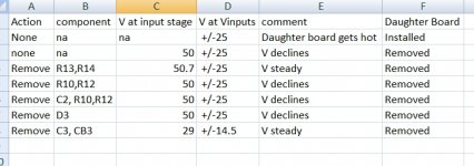
I removed the daughter board for further testing. The table below shows the voltages measured either at the VPOS/VNEG to GND.P or at terminals 1 to 3 of where the daughter board bolts on.
I removed the C60 thermistors and safety cap from the mains side to ensure they are not part of the problem while testing.
The voltage will hang at about 50V for about 10seconds, then rapidly fall off to about 30V.
When the voltage drops below about 40V, the fan will start to slow down.
I went ahead and replaced all the solid state components on general principles (Both MOSFETS, Q5, Q6, Q7, and C2 which got damaged on removal).
I tested D3 off the board, it tests good. D1, D2 test good on the board.
There is no odor or indication of physical damage to any component.
All the resistors are Vishay milspec parts, and measure correctly on the board.
The only part I have not tested directly is the Edcor, but the problem persists even with the daughter board and C2 removed.
I know I must be missing something really obvious.
Either there is an issue with the power supply, or one of the resistors is failing only under load with no other outward sign.
The power supply is a full rework - the old one used a pair of block rectifiers, the new one uses discreet MUR3020 diodes.
I have checked some of the more obvious things with the power supply. The footprints are correct, there are insulating pads between the diode and sink, it does output -25V 0V +25V.
Any help with this would be greatly appreciated.
Thanks,
-Josh
Sorry I have chimed in for a while, I have been upside down with work and projects.
I have a real mess (of my own making) that I hope you all can help me straighten out.
I completed the M2 last winter, and I have been loving it - it is an exceptional amp.
I put everything together as a prototype for the final assembly of the amplifier, and I am just now getting around to wrapping up the project. Up until now, the power supply and micro-controller boards have been done point-to-point on perf board.
I designed boards for the power supply, DC protection, and microntroller, and had them made up by JLCPCB.
Please see the block diagram for the layout. I have also included the PS schematic (basically the same stuff we all use), a table with test results, and the official M2 schematic so folks won't have to dig it out of their files.
So here is the story:
I populated the power supply, verified I am getting +/- 25 DCV at the outputs. I installed it into the amp, and started it with my 150W lightbulb current limiter. Everything seemed fine.
I move the amp to my listening room and hooked it up to my pre-amp and speakers with out the 150W bulb (the dumber move is to follow...)
No sound (I have issues at times with my network, and often have to fuss with my NAS to get sound).
I played around for a bit, and still got no sound.
I then switched the polarity of the power supply to the amp - the fuses blew instantly.
I can only credit this stupidity to being exhausted, it being late at night, and a momentary bout of psychosis...
Later that week, it took it back upstairs for some testing (using the 150W bulb).
The first thing I found was that the (Norwood) daughter board gets very hot very fast.
I removed the daughter board for further testing. The table below shows the voltages measured either at the VPOS/VNEG to GND.P or at terminals 1 to 3 of where the daughter board bolts on.
I removed the C60 thermistors and safety cap from the mains side to ensure they are not part of the problem while testing.
The voltage will hang at about 50V for about 10seconds, then rapidly fall off to about 30V.
When the voltage drops below about 40V, the fan will start to slow down.
I went ahead and replaced all the solid state components on general principles (Both MOSFETS, Q5, Q6, Q7, and C2 which got damaged on removal).
I tested D3 off the board, it tests good. D1, D2 test good on the board.
There is no odor or indication of physical damage to any component.
All the resistors are Vishay milspec parts, and measure correctly on the board.
The only part I have not tested directly is the Edcor, but the problem persists even with the daughter board and C2 removed.
I know I must be missing something really obvious.
Either there is an issue with the power supply, or one of the resistors is failing only under load with no other outward sign.
The power supply is a full rework - the old one used a pair of block rectifiers, the new one uses discreet MUR3020 diodes.
I have checked some of the more obvious things with the power supply. The footprints are correct, there are insulating pads between the diode and sink, it does output -25V 0V +25V.
Any help with this would be greatly appreciated.
Thanks,
-Josh
Attachments
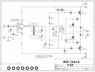
It seems to me that removing R10 and R12 from the amplifier PCB will completely disable the bias network, which will lead to disaster. With those resistors removed there's no input current flowing in Q5, so there's no output current either. R6 pulls up Q1's gate to +infinity and Q1 conducts +infinity amps. At the same time R7 pulls down Q2's gate to minus infinity and Q2 conducts minus infinity amps. It happens slowly because R6 and R7 are charging an enormous capacitor C3 as they turn on the MOSFETs.
I don't know whether the amp board has damaged the power supply, or whether the power supply has damaged the amp board, or both are damaged. You'll need to find a way to test and verify them one at a time, i.e., divide and conquer.
Wait to see what other members have to say; perhaps I'm looking at it all wrong, and perhaps other folks will set you (and me) straight.
It seems to me that removing R10 and R12 from the amplifier PCB will completely disable the bias network, which will lead to disaster. With those resistors removed there's no input current flowing in Q5, so there's no output current either. R6 pulls up Q1's gate to +infinity and Q1 conducts +infinity amps. At the same time R7 pulls down Q2's gate to minus infinity and Q2 conducts minus infinity amps. It happens slowly because R6 and R7 are charging an enormous capacitor C3 as they turn on the MOSFETs.
I don't know whether the amp board has damaged the power supply, or whether the power supply has damaged the amp board, or both are damaged. You'll need to find a way to test and verify them one at a time, i.e., divide and conquer.
Wait to see what other members have to say; perhaps I'm looking at it all wrong, and perhaps other folks will set you (and me) straight.
Thanks for the reply.
I should clarify the order of operations.
I performed the checks on the amp up to removing D3 with the old parts. After that, it seemed most likely that one of the solid state devices was bad.
Since the parts are not terribly expensive, I just replaced all of them.
When the problem persisted, I removed D3, tested. I then removed C3, and CB3 after re-installing D3.
I agree it looks like removing R10 and R12 might affect either the MOSFETS or Q5, but those parts have all been replaced now. As it sits, only C3, and CB3 are removed.
Thanks
-Josh
I have an update.
I removed the Edcor, it seems fine, and the problem persists.
So i put the Edcor and C3 back in - I left CB3 off.
I removed the 4 caps in the power supply between the diodes and the resistors, and jumpered in DC from the old rectifier blocks. no change.
I put the 4 caps I removed from the PS into a new board with only some headers to attach wires to. No change.
This is about a simple as I can make the PS, it is just a toroid, a rectifier assembly (known good), and 2 caps per rail.
I found a 400VA transformer in my cabinet that has 15V secondaries and tried it. This produces ~20.5V per rail, which should be good enough for testing purposes. It behaved the same, though it took a few seconds longer before the voltage started to drop (As expected).
For good measure, I also disconnected the transformer that runs the micro controller.
I could really use some suggestions.
Thank you,
-josh
- Home
- Amplifiers
- Pass Labs
- The diyAudio First Watt M2x