I've ordered the M2X boards and am about to order the Edcor transformers. The Edcor site notes:
Availability: Product is built to order.
Ship date: 8 weeks
Have orders actually been taking 8 weeks or are they being overly conservative?
I have an extra pair of Edcors on hand, should you find yourself with the boards complete but awaiting transformers, I'll send you mine and you can send me the pair you ordered when they arrive if you'd rather not wait.
Just as we were putting the set of M2x PCBoards into the diyAudio Store, I telephoned Mrs. Edcor (marketing dept) and told her to expect an increase in orders for those particular transformers. "We are making another Nelson Pass design available at low cost, which uses two of your PC600-15K transformers, and we expect that LOTS of people will buy them." Not surprisingly she knew the name. I have a feeling they keep more of these particular transformers in inventory, and launch new production runs sooner, than for other transformer products they sell. That's my guess anyway.
"We are making another Nelson Pass design available at low cost, which uses two of your PC600-15K transformers, and we expect that LOTS of people will buy them."
Oh another NP amp coming up
")
I think Mark is referring to this project, the M2X. The previous one is teabags M2 boards.
Oh ok got it thanks
In case anybody wants to analyze the Austin circuit and hand calculate its current draw when VCC is +23V and VEE is -23V, I've attached an annotated schematic below.
Austin's supply current is the sum of four individual contributions:
- I1 is the current which flows through current source transistor Q4 and input follower transistor Q2
- I2 is the current which flows through Q3 and Q1
- I3 is the current which flows through the bias generator, IC1 + R7 + IC2
- I4 is the current which flows in the output stage, through Q5 and Q6
Please enjoy!
_
Thanks to both @Mark Johnson and @Elwood625 for the previous posts and some tips re: measuring/testing the IPSs before installation.
I am fairly sure I grasp some, but clearly not all of the basics. I am still a bit lost and apprehensive re: the actual test points and potentially the proper process to ensure proper current draw. I don't want to just go poking around on the board.
What I've done so far is:
1) Set up my bench supply for 25.00VDC (verified with DMM) and current limited the bench supply to roughly 0.02A. That's about as low as it will go. The display I have only displays to the 100th of an Amp, and I am not sure how precise / accurate it is. No spec in the manual gives me guidance. I am not sure if current limiting the supply actually provides any safety net, but it made me feel better.
2) Checked the Mountain view boards briefly by applying +25VDC between I/O 1 and I/0 3. Positive to 3 and Ground to 1.
Verified that there's no magic smoke, no smells or anything that looks off. A lovely glowing red LED.
I'd like to learn a bit more re: how to measure the current draw. I reviewed the schematic, along with the previous posts. Clearly I incorrectly assumed that I'd measure between I/0 points 1 and 3. I checked between I/O 1 and I/O 3 and got no current. So, I stopped. I am using the DMM properly set to mA/uA scale with the leads in the proper locations on the DMM.
Any assistance to understand where the proper test points are on the boards for the overall current draw is appreciated. Any other thoughts for errors are also welcome. Still learning...
but 
Last edited:
Edcor could make a special DIY forum version using Amorphous or Mu-metal core.....or another exotic material…..for same price? ….then we could listen to different core material?
I think it's best to leave the choice of lamination material to the experts - Edcor in this case. Silicon steel is the preferred metal for cores. Mu-metal is for shielding and in my opinion a poor choice for transformer laminations.
Silicon steel is probably perfect for Edcor but I know that e.g. Lundahl makes cores with both Amorphous material and mu-metal for their phono step-up transformers. These core material seems good if current is low. So for Edcor…..even current seems low....it may not be low enough for these cores....or the transformer may get too large in size…...but I am not a transformer experts…...so let us leave it to Edcor ...Amorphous core and pure silver wire then price would be higher than a few USD's.
...Amorphous core and pure silver wire then price would be higher than a few USD's.OK - We're making more progress. Thanks again!
With the exception of Tucson (still waiting on DIP8 sockets), I checked the current draw on all the IPSs.
Ishikawa - 6.8 and 6.6 mA
Mountain View - 24.5 and 24.5 mA
Austin - 8.6 and 8.3 mA
Norwood - 0.26 and 0.17mA. When I dropped the range into uA - they varied quite a bit. One seemed to balance around 250uA and the other around 160uA.
No smoke or smells or anything suspicious. I left them all on the bench for a minute or so each.
Is it because Norwood is SMD that it's so much lower than the rest? Is there something I should be concerned with? I did not find any previous references to expected values.
As always, thanks to all!
Just found out my chassis should be here next week. It got delayed about 4 days due to the shipper not sending along some paperwork to FedEx.
With the exception of Tucson (still waiting on DIP8 sockets), I checked the current draw on all the IPSs.
Ishikawa - 6.8 and 6.6 mA
Mountain View - 24.5 and 24.5 mA
Austin - 8.6 and 8.3 mA
Norwood - 0.26 and 0.17mA. When I dropped the range into uA - they varied quite a bit. One seemed to balance around 250uA and the other around 160uA.
No smoke or smells or anything suspicious. I left them all on the bench for a minute or so each.
Is it because Norwood is SMD that it's so much lower than the rest? Is there something I should be concerned with? I did not find any previous references to expected values.
As always, thanks to all!
Just found out my chassis should be here next week.
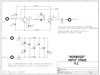
It got delayed about 4 days due to the shipper not sending along some paperwork to FedEx.I greatly fear that you are trying to operate Norwood at an illegally low total supply voltage. Consider what's actually on a Norwood board (shown below). If you apply only 25V between pin 1 and pin 3, because that's the highest your power supply will go, then what voltage is applied to the integrated circuits themselves (VUPPER minus VLOWER)?
D3 and D4 are 12V zener diodes. Thus 12V is dropped across D3 and another 12V is dropped across D4. Leaving how much for (VUPPER minus VLOWER)?
The M2x daughter cards are designed for about 38V (min) to 50V (max) between the bolts called pin1 and pin3. "Testing" them at only 25V may not tell you very much.
_
Attachments
I greatly fear that you are trying to operate Norwood at an illegally low total supply voltage. Consider what's actually on a Norwood board (shown below). If you apply only 25V between pin 1 and pin 3, because that's the highest your power supply will go, then what voltage is applied to the integrated circuits themselves (VUPPER minus VLOWER)?
D3 and D4 are 12V zener diodes. Thus 12V is dropped across D3 and another 12V is dropped across D4. Leaving how much for (VUPPER minus VLOWER)?
The M2x daughter cards are designed for about 38V (min) to 50V (max) between the bolts called pin1 and pin3. "Testing" them at only 25V may not tell you very much.
_
I pondered over this for awhile. Clearly I have a ton to learn. I tried to apply the process I thought I understood for the Austin card and @Elwood625's previous posts to test all the boards. I'm sure the more experienced folks are having a chuckle. I don't mind. A guy's gotta learn. I will continue to work on my fundamentals.
I can use another bench supply that can go up to 50 VDC. Is it the proper process to check each of them at 50 VDC applied across pin one and pin 3? Do I need to apply a voltage across pins 1 and 4 on any of the boards? That goes against what I thought I had understood. Of course I want to understand how it all works (eventually), but for now, I want to make sure that I check the daughter boards as well as I can before attaching even the first one to the amp boards. Breaking something through poor testing / verification would be a drag.
I'll always try to answer the questions thoughtfully.
I think we'd only have 1V after D3 and D4. That was an "aha". I'm at a loss for how the side of the circuit with Pin 2 and pin 4 ties to 1 and 3 through the amp board (even when I sit the amp board and the Norwood schematics side by side.
I fear it's over my head for the time being, but I'll keep plugging.
Thanks as always.
- Patrick
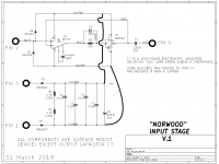
I'm at a loss for how the side of the circuit with Pin 2 and pin 4 ties to 1 and 3 through the amp board (even when I sit the amp board and the Norwood schematics side by side.
Note how "VUPPER" and "VLOWER" exist on the power section and the amplifier section of Norwood. These are common to each other, but the connections are not drawn in the interest of keeping lines to a minimum. I drew them below.
What Bob, Carol, Dave, and Alice are doing, we still don't know... Enjoying music, I'd guess...
Attachments
Last edited:
Patrick - The M2X uses a power supply of +24vds, -24vdc and ground. The boards use +24vdc and -24vdc on pins 1 & 3. My power supply is +24vdc and ground, so that is how I tested my boards. Good news, they all work in the amp, bad news, catching the stainless star washers. I didn't build Norwood, so I can't help you there. What the "proper" +24vdc and ground test voltage should be, no clue.
I know what Bob, Carol, TED, and Alice are doing, Definitely enjoying beautiful music!
I know what Bob, Carol, TED, and Alice are doing, Definitely enjoying beautiful music!
Thanks Mark, Jim, and @Elwood625.
I still haven't completely absorbed it. I feel confident that the boards will function as intended. The build guides are great, and with my level of skill (or lack thereof) I was very careful building them. I've been trying to check as much as I can in isolation for both safety and sanity. The "why" they work the way they work will continue another day.
@Elwood625 - Thanks for helping! Interesting about the star washers catching. I have post #828 saved in my notes and was considering some of the alternate parts.
Alice, Bob, Carol, Dave .....
Once upon a time long ago, I put a circuit schematic into a CAD system and used its layout editor to create a PCB. I clicked the "Connectivity Error Checking" button and the CAD system told me: No hookup errors, the PCB layout exactly matches the schematic. Feeling relieved, I sent the files to a PCB fab house and got my boards back in a few weeks.
But the circuit didn't work.
Eventually I traced it down to a schematic error. Somehow the schematic editor had let me make a T-intersection between a horizontal wire and a vertical wire, without electrically connecting the wires. They were two different "nets" / two different circuit "nodes". The PCB perfectly matched this erroneous schematic so the PCB was a perfect implementation of an error.
I was angry. The CAD system fooled me into thinking everything was okay, and I determined to never let this type of non-connection error happen again.
So I decided to give every node in the schematic a name myself, and not allow the system to assign them (no more "Net_1447003" anonymous nodes for me!). Now I can do a quick eyeball scan down the netlist and make sure that all nodes have human-created names. If I ever see "Net_1447003" then I instantly know it is a schematic error. Aha you basxtard CAD system I caught you!
Thus I got into the habit of naming every node. Saved my buttt a few times so it was worth the small extra effort. Sometimes I do it alphabetically like Alice, Bob, Carol, Dave and so forth. It's an old habit and hard to get rid of, even though I don't use that CAD system any more and even though the one I use now (KiCad) seems relatively bug free.
- Home
- Amplifiers
- Pass Labs
- The diyAudio First Watt M2x