Pass DIY Addict
Joined 2000
Paid Member
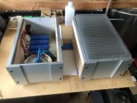
Why is there tape on your transformer?
Masking tape on the shield , leaving it as I have not finished the chassis yet. Feet yet to be attached.
About IEC filter , it is 10A filter, more than 3 times the amplifiers rating. Well, just in case there is ghosts coming through line to damage my amp.
Hi. I have the aleph j kit but would rather build the F2j amp instead. I think it will be closer to what I am looking for. I have asked Kinku if he has anymore pcbs but he doesn’t. So, does anyone have the pcbs that they are not going to use, or are there another 4 people who want to build the amp so that he can get another 5 sets made.
Have a great Xmas yAll.
Ta
Have a great Xmas yAll.
Ta
I’ve been very slowly plugging away on this F2J project.
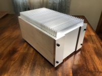
I decided to make a pair of mono blocks from some cases I originally started thinking they would only hold power supplies. The cases are approximately equivalent to half a 4U. The heatsinks are 12” X 7”. They may require fans installed in the case or a babysitter underneath.
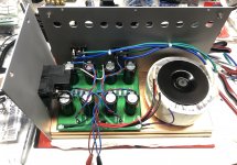
I’ve gotten to the point where I’ve assembled and fitted a power supply in one case. I was going to try a point to point supply with some large surplus caps I’ve had from Apex Jr for a while. Unfortunately, they seemed to create too many issues with layout in the case due to its size.
I decided to instead use the power supply boards that kinku offered with these F2/F2J boards after I figured out a way to mount them in the case with all the other components.
I had purchased extra supply boards so I am able to use one for each case and connect both the dc outputs from each supply board in parallel.
So the first supply is up and running. I tested the dc output and I only get between 20 and 21 volts.
I think this has to do with variations in the AC voltage I get from the wall outlet and also the fact that the supply doesn’t have the load of the amp circuit applied to it yet?
I just wanted to check before moving on to build the second supply.
I decided to make a pair of mono blocks from some cases I originally started thinking they would only hold power supplies. The cases are approximately equivalent to half a 4U. The heatsinks are 12” X 7”. They may require fans installed in the case or a babysitter underneath.
I’ve gotten to the point where I’ve assembled and fitted a power supply in one case. I was going to try a point to point supply with some large surplus caps I’ve had from Apex Jr for a while. Unfortunately, they seemed to create too many issues with layout in the case due to its size.
I decided to instead use the power supply boards that kinku offered with these F2/F2J boards after I figured out a way to mount them in the case with all the other components.
I had purchased extra supply boards so I am able to use one for each case and connect both the dc outputs from each supply board in parallel.
So the first supply is up and running. I tested the dc output and I only get between 20 and 21 volts.
I think this has to do with variations in the AC voltage I get from the wall outlet and also the fact that the supply doesn’t have the load of the amp circuit applied to it yet?
I just wanted to check before moving on to build the second supply.
Attachments
I was hoping to get some feedback on some F2/F2J questions I have.
I finished building the second power supply for my monoblocks and all looks well enough.
The voltage level after rectification and filtering is the same with both supplies. After finishing the second supply and retesting both I ended up at about 22V with no load.
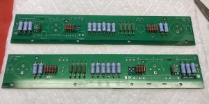
I’m now stuffing the amp boards and I have reached a point where I want to make sure I’ve populated all the smaller stuff correctly before moving onto the caps and etc.
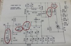
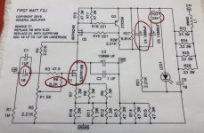
I printed out the diagrams for both the F2 and F2J circuits. I’ve attached images of them and circled areas of the circuits I have questions about.
I am building the F2J.
In reviewing the directions noted on the F2J circuit diagram, and looking at the F2 diagram as well, I noticed that there are a few differences that are not explained.
The first F2J note states “REMOVE Z1”. However R2 also appears to have been removed along with Z1.
I’m not an electrical engineer. I don’t know what these two components do in conjunction with each other, or the circuit, other than they appear wired in series and were both removed from the F2J diagram.
I’m trying to follow what I think is the correct modifications for the F2J. I didn’t populate Z1 or R2 based on what I see in the F2J diagram.
Is this the correct thing to do? Also, do I need to place any jumpers where Z1 and R2 were located in the circuit?
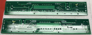
I’ve attached pictures of the top and bottom of the amp boards as they are currently populated. The little green arrows of tape on the underside indicate the location of Z1 and R2 in the circuit.
The other instructions on the F2J diagram were to replace R6 with a value of 8.2K...no problem. Replacing Q1 with SJEPR100 will happen when I am ready to mount the boards on the heatsinks.
The final note states to add a 10uF cap to the underside of the boards at C1 whose value is 1uF.
I will have to get creative with C1 because the manner in which I am mounting my boards in the cases does not allow enough clearance for the larger cap to be bottom mounted. I think I can pull off tucking the smaller 1uF cap under the boards and put the larger 10uF cap on the top side.
Beyond the changes indicated by the notes, I noticed a discrepancy in the F2 and F2J diagrams at R22 and C4.
I’m not concerned about R22 as its just a limiting resistor for the LED that I can use an online calculator to determine the value of based on the LED I use.
I am wondering about the difference of C4’s value in the two diagrams.
I’m not sure why there is such a big difference in the value used at C4 in the F2 as opposed to the F2J (1000uF vs 15000uF).
There is no note regarding a difference at C4.
Kinku’s board appears to be designed for the smaller cap. I can’t make out the value of C4 in his pics. It does appear to be a smaller cap.
I ordered a 1000uF with proper spacing. Unless this was a typo, or anyone can tell me otherwise, I will assume it is the correct value to use at C4 for the F2J.
Thanks in advance for any guidance.
I finished building the second power supply for my monoblocks and all looks well enough.
The voltage level after rectification and filtering is the same with both supplies. After finishing the second supply and retesting both I ended up at about 22V with no load.
I’m now stuffing the amp boards and I have reached a point where I want to make sure I’ve populated all the smaller stuff correctly before moving onto the caps and etc.
I printed out the diagrams for both the F2 and F2J circuits. I’ve attached images of them and circled areas of the circuits I have questions about.
I am building the F2J.
In reviewing the directions noted on the F2J circuit diagram, and looking at the F2 diagram as well, I noticed that there are a few differences that are not explained.
The first F2J note states “REMOVE Z1”. However R2 also appears to have been removed along with Z1.
I’m not an electrical engineer. I don’t know what these two components do in conjunction with each other, or the circuit, other than they appear wired in series and were both removed from the F2J diagram.
I’m trying to follow what I think is the correct modifications for the F2J. I didn’t populate Z1 or R2 based on what I see in the F2J diagram.
Is this the correct thing to do? Also, do I need to place any jumpers where Z1 and R2 were located in the circuit?
I’ve attached pictures of the top and bottom of the amp boards as they are currently populated. The little green arrows of tape on the underside indicate the location of Z1 and R2 in the circuit.
The other instructions on the F2J diagram were to replace R6 with a value of 8.2K...no problem. Replacing Q1 with SJEPR100 will happen when I am ready to mount the boards on the heatsinks.
The final note states to add a 10uF cap to the underside of the boards at C1 whose value is 1uF.
I will have to get creative with C1 because the manner in which I am mounting my boards in the cases does not allow enough clearance for the larger cap to be bottom mounted. I think I can pull off tucking the smaller 1uF cap under the boards and put the larger 10uF cap on the top side.
Beyond the changes indicated by the notes, I noticed a discrepancy in the F2 and F2J diagrams at R22 and C4.
I’m not concerned about R22 as its just a limiting resistor for the LED that I can use an online calculator to determine the value of based on the LED I use.
I am wondering about the difference of C4’s value in the two diagrams.
I’m not sure why there is such a big difference in the value used at C4 in the F2 as opposed to the F2J (1000uF vs 15000uF).
There is no note regarding a difference at C4.
Kinku’s board appears to be designed for the smaller cap. I can’t make out the value of C4 in his pics. It does appear to be a smaller cap.
I ordered a 1000uF with proper spacing. Unless this was a typo, or anyone can tell me otherwise, I will assume it is the correct value to use at C4 for the F2J.
Thanks in advance for any guidance.
Attachments
-
 EFDA1561-39DE-4497-8969-57664676D3B3.jpg980.7 KB · Views: 469
 -
 D808332C-4571-4C2E-8DA6-684F8E002565.jpg494 KB · Views: 226
 -
 E8A3AF76-10E5-4FEB-A317-3602F86F93F5.jpg618.6 KB · Views: 461
 -
 D09E774A-DE0D-494C-A0B2-2F35417998A6.jpg778.1 KB · Views: 214
 -
 D3A8188C-2C77-4824-ADBC-78A626FF9125.jpg803.8 KB · Views: 180
Hello Chromenuts,
I also used Kinku's boards, so they will work.
Don't worry about Z1 and R2, removing Z1 leaves R2 without function, so no jumper. ZI is for safety in case you use the IRF Mosfets, not necessary with Semisouth. C1 is changeable, I put the 10µ from RCA to PCB, there is no space for my 10µ Con the PCB.
C4 is a C in parallel to the 15.000µ, only on early diagrams, not essential, so also, don’t worry.
R22 is about 10k, preferably 1W or more (I use 3 W).
And, yes, Kinku choose a small 15,000µ C for coupling.
UFW1V153MRD Nichicon | Mouser
I don’t really understand your power supply. I see 2 bridge rectifiers for each channel. This amplifier doesn’t need a symmetrical voltage. I have 2 boards in one case, a 300W toroid with 2X18V AC. Each for 1 channel, with the applied load (the amplifier boards) I get about 23 V DC. Maybe your bleeder resistor is too small in value?
Br
Helmut
Hi Helmut
Thanks for sharing that information and your experience with the F2J and these boards.
I figured Z1 and R2 were a non-issue, but it’s good to get confirmation on that.
During my research on putting together a bill of materials for this amp there was a lot of debate as to what was really required regarding a variety of the caps in the circuit.
I guess since I already ordered the 1000uF cap called for at C4 in the F2J diagram I was using, and it’s the correct size and pitch, I’ll just use that for now.
The power supplies are single rail (+24 and GND) in design. They are based on the boards kinku offered along with these F2/F2J boards which were designed for a stereo amp.
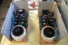
I decided to build mono blocks. Since I already had Antek transformers with dual primaries and secondaries, and these PS boards fit in the cases, I simply populated both sides of these stereo supply boards, used a rectifier for each channel and tied the outputs together in parallel. I’m still left with a single rail supply, I just have the benefit of some additional capacitance for each mono block.
Thanks for sharing that information and your experience with the F2J and these boards.
I figured Z1 and R2 were a non-issue, but it’s good to get confirmation on that.
During my research on putting together a bill of materials for this amp there was a lot of debate as to what was really required regarding a variety of the caps in the circuit.
I guess since I already ordered the 1000uF cap called for at C4 in the F2J diagram I was using, and it’s the correct size and pitch, I’ll just use that for now.
I don’t really understand your power supply. I see 2 bridge rectifiers for each channel. This amplifier doesn’t need a symmetrical voltage.
The power supplies are single rail (+24 and GND) in design. They are based on the boards kinku offered along with these F2/F2J boards which were designed for a stereo amp.
I decided to build mono blocks. Since I already had Antek transformers with dual primaries and secondaries, and these PS boards fit in the cases, I simply populated both sides of these stereo supply boards, used a rectifier for each channel and tied the outputs together in parallel. I’m still left with a single rail supply, I just have the benefit of some additional capacitance for each mono block.
Hello, I wonder if that F2J is still better option than ACA (higher voltage version called 'premium parts') in order to drive a high sensitivity/ high impedance 8'' fullrange speaker? (Rullit Classic 8'' coupled by a front horn)
F2J would be an ideal choice as being 100% current output, non feedback.
ACA for some reason has deserved more praise and refinements, but is arranged as common source output / a bit feedback, not the same.
Thanks in adv,
Jordi
F2J would be an ideal choice as being 100% current output, non feedback.
ACA for some reason has deserved more praise and refinements, but is arranged as common source output / a bit feedback, not the same.
Thanks in adv,
Jordi
Attachments
- Home
- Amplifiers
- Pass Labs
- F2J clone Build thread