Hi All,
I am looking for 8ohm@20W amplifier.
1. My speakers are rated at 8ohm@20W. But ALEPH3 has 8ohm@30W.
2. ALEPH3 has 200W power dissipation. My required 8ohm@20W can lower power dissipation to 160W.
3. ALEPH3 has bias 1A in each output stage. And matching is required for parallel output.
I can lower components and can increase bias to 1.5A so it will reduce distortion and improve sound quality.
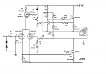
4. I removed protection circuit as it not required.
5. lowered zener diode series resistance as suggested by NP.
6. I replaced MPSA18 with ZTX450 as MPSA18 not available.
7. INPUT IRF9610 replaced by FQP3P20 as suggested(Toshiba but not available) by NP.
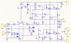
It is a mini -aleph with modifications suggested by NP.
I don't have experience in choosing R11 resistor value so I copied from another ALEPH circuit.
So please suggest if any modification is required to achieve above.
It is a mini aleph with modifications suggested by NP.
Thanks,
Nag.
I am looking for 8ohm@20W amplifier.
1. My speakers are rated at 8ohm@20W. But ALEPH3 has 8ohm@30W.
2. ALEPH3 has 200W power dissipation. My required 8ohm@20W can lower power dissipation to 160W.
3. ALEPH3 has bias 1A in each output stage. And matching is required for parallel output.
I can lower components and can increase bias to 1.5A so it will reduce distortion and improve sound quality.
4. I removed protection circuit as it not required.
5. lowered zener diode series resistance as suggested by NP.
6. I replaced MPSA18 with ZTX450 as MPSA18 not available.
7. INPUT IRF9610 replaced by FQP3P20 as suggested(Toshiba but not available) by NP.
It is a mini -aleph with modifications suggested by NP.
I don't have experience in choosing R11 resistor value so I copied from another ALEPH circuit.
So please suggest if any modification is required to achieve above.
It is a mini aleph with modifications suggested by NP.
Thanks,
Nag.
Attachments
with 15Vac secondaries , there will be around 18Vdc at rails
with Iq 1A ....... dissipation will be 36W per channel
resulting power will be around 15W/8R , with rails as limiting factor
just make regular Aleph 30 , with just one pair of outputs
18Vac secondaries , resulting in 22V5dc rails
set Iq to your liking , say 1A for starters ...... then up until you hit what you want - either desired dissipation or temp of 50C at heatsinks or max dissipation of some 40W per mosfet
post Aleph 30 schematic here ....... that amalgam you made is ...... wrong in enough places")
with Iq 1A ....... dissipation will be 36W per channel
resulting power will be around 15W/8R , with rails as limiting factor
just make regular Aleph 30 , with just one pair of outputs
18Vac secondaries , resulting in 22V5dc rails
set Iq to your liking , say 1A for starters ...... then up until you hit what you want - either desired dissipation or temp of 50C at heatsinks or max dissipation of some 40W per mosfet
post Aleph 30 schematic here ....... that amalgam you made is ...... wrong in enough places
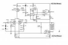
now :
- change R108 to 270R and add trimpot of 500R in series
- change R113 to 39K , add 100K trimpot in series
make these changes , then put connecting dots on all connecting points and post it , just that we are sure that you're getting it all
you need just two 0R47 resistors in output rail , so remove 2 of them
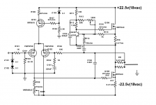
I actually did a similar thing (built on BrianGT boards): started out as Aleph Mini, but morphed into an "Aleph10" or "Aleph Single" or whatyawannacallit ...
It is an Aleph30 with a single set of outputs. I used IRFP140s with source resistors of 0.22 Ohms (and sense resistors with a resulting resistance of 0.11 Ohms).
Run with either +/- 19V rails at 2.2A bias, or +/- 24V rails at 2.0A bias.
Both worked very well. No stability or drift problems. I preferred the sound of the 19V / 2.2A version, but have speakers that are a very easy load.
Also excellent suggestions by Zen Mod to add the trimmers - that will allow you to easily adjust bias and offset.
Best regards,
Claas
Some tips to optimize this variant of Aleph 3
Hi Guys ...Please what do you think about this Chinese variant of Aleph 3?
Some advice for optimizer it?
This are the Mister NP advices:
"No surprises. Varying the gain of the current source has a substantial effect
on the sound. As you increase the gain, the open loop gain of the amplifier
increases, so distortion goes down and becomes more 3rd harmonic in
character. As you decrease the gain of the current source toward having
constant DC current, the open loop goes down, there is less feedback,
the distortion goes up and is mostly negative phase 2nd harmonic.
Playing with the current source gain (either Aleph or mu-follower circuits)
also impacts the efficiency. If you are simply looking to maximize efficiency,
then the 50% gain figure is close to what you want - the current source is
seen to contribute 50% of the AC output current. With this the actual
efficiency of the amplifier will be 40% at best for real circuits.
When you deviate from 50% you will find that you need to increase the
bias current to have symmetric clipping, but you pick up some interesting
performance aspects:
If you double the current and the gain of the current source, what used to
be the gain transistor has very little work to do, and actually becomes more
like a driver transistor for the current source. The distortion gets much
lower, but higher order harmonic content.
If you double the current and set the current source as constant (0 gain)
then the distortion becomes more purely 2nd and continues to get lower.
This setting tends to sound quite good.
Of course in both cases the efficiency drops by half, so you're getting down
to 15% to 20% instead of 30% to 40%"
Thanks Mister Pass!
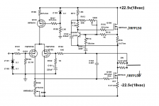
I need to optimizer this amp for good load capability but with a second harmonic thd predominant .
It is possible playng with Bias setting and AC gain?
I will use 2sj313 instead Q5 and Q6 , mpsa18 instead Q4 and Q9.
Thanks.
Hi Guys ...Please what do you think about this Chinese variant of Aleph 3?
Some advice for optimizer it?
This are the Mister NP advices:
"No surprises. Varying the gain of the current source has a substantial effect
on the sound. As you increase the gain, the open loop gain of the amplifier
increases, so distortion goes down and becomes more 3rd harmonic in
character. As you decrease the gain of the current source toward having
constant DC current, the open loop goes down, there is less feedback,
the distortion goes up and is mostly negative phase 2nd harmonic.
Playing with the current source gain (either Aleph or mu-follower circuits)
also impacts the efficiency. If you are simply looking to maximize efficiency,
then the 50% gain figure is close to what you want - the current source is
seen to contribute 50% of the AC output current. With this the actual
efficiency of the amplifier will be 40% at best for real circuits.
When you deviate from 50% you will find that you need to increase the
bias current to have symmetric clipping, but you pick up some interesting
performance aspects:
If you double the current and the gain of the current source, what used to
be the gain transistor has very little work to do, and actually becomes more
like a driver transistor for the current source. The distortion gets much
lower, but higher order harmonic content.
If you double the current and set the current source as constant (0 gain)
then the distortion becomes more purely 2nd and continues to get lower.
This setting tends to sound quite good.
Of course in both cases the efficiency drops by half, so you're getting down
to 15% to 20% instead of 30% to 40%"
Thanks Mister Pass!
I need to optimizer this amp for good load capability but with a second harmonic thd predominant .
It is possible playng with Bias setting and AC gain?
I will use 2sj313 instead Q5 and Q6 , mpsa18 instead Q4 and Q9.
Thanks.
Attachments
why dont'ya ask Chinese vendor for advices ?

Just done... He not reply.
- Status
- This old topic is closed. If you want to reopen this topic, contact a moderator using the "Report Post" button.
- Home
- Amplifiers
- Pass Labs
- Medium Aleph 3 8ohm@20w.