hi,
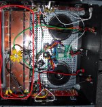
After struggling to do a DIY board, I have decided to use wire. I am attaching how I am going to assemble F5T V2 (PSU from F5 manual), please let me know if you see any major flaw.
I have a hard time visualizing circuits, so wanted someone to ok.
Thankyou
After struggling to do a DIY board, I have decided to use wire. I am attaching how I am going to assemble F5T V2 (PSU from F5 manual), please let me know if you see any major flaw.
I have a hard time visualizing circuits, so wanted someone to ok.
Thankyou
Attachments

Last edited:
")
Ok, in that case you could build two separate supplies, one for each rail and connect them in series at the output, is that what you have tried to do in your diagram? It looks like it, it's just a slightly confusing way of drawing it, but it is basically correct.
Last edited:
If I connect in series V+, V- will only be at one end and not at same distance from amp PCB's. My transformer has large diameter and thinking of placing them horizontally like this (. are caps , above that is big transformer, X- space)
___________
|TTTTTTTTTT|
|TTTTTTTTTT|
|RRRRRRRRR|
|ANSFORMER|
|XXX....XXXX|
|XXX....XXXX|
|XXXXXXXXX|
i'll lay one over the other(exactly as shown in attachment) so :
1. They are at same distance from both amp PCB's. I have V+, V- on both sides for left and right amp PCB.
2 So I can twist V-, V+ and GND which goes to amp PCB left and right.
Last edited:
no need for thermal conduction
Thankyou,
In that case I'll just use a ceramic tile that wont break easily.
- Status
- This old topic is closed. If you want to reopen this topic, contact a moderator using the "Report Post" button.
- Home
- Amplifiers
- Pass Labs
- PSU Query