Are those positions at the ground plane? Do you have more photos?
Ground pads are harder to solder because the copper mass becomes a heatsink during soldering.
I just built my fourth (!) Whammy, and I can confirm that happens with the pads that are on the ground plane.
I used an electrical soldering iron that goes so hot the metal turns red. It helps to attach the heatsinks and some very very quick ground plane soldering.
The noise floor sounds slightly higher compared to my other amps but inaudible on low sensitivity headphones.
One problem it has though is some low level high pitched intermittent whine. It does go away on low sensitivity headphones too so I haven't pursued it. Maybe I should one of these days.
The noise floor sounds slightly higher compared to my other amps but inaudible on low sensitivity headphones.
One problem it has though is some low level high pitched intermittent whine. It does go away on low sensitivity headphones too so I haven't pursued it. Maybe I should one of these days.
for soldering of greater mass parts - temperature isn't crucial
what is crucial - tip big enough to have enough thermal inertia
recently I soldered 4mmsq wires , on Buddy's little river boat, with 12V/15W soldering iron
but, it have 9mm Dia tip with cone end
go figure
my regular praxis for bigger parts (including TO247 output device pins) is temp cranked to 480, with 8mm wide chisel tip
fast, efficient, clean
Are IRF630 and IRF9630 suitable for this project?
Sorry, actually i want to know if the IRF620 and IRF9620 is suitable here.
Have you tried applying some solder flux to the pads? Your iron might not be hot enough and/or not recovering well when you touch the pads. All of these problems were solved for me when I started using The Fire Metall solder from the store. Richard has done a fantastic job tuning the recipe in to the point where its the only solder I use.
--Tom
unfortunately that solder was out of stock when I ordered my parts but I got something from digikey that had pretty much the same make up. I believe it's the ground pads but I have tried with as much heat as I was comfortable with (360 degrees celcius) to no luck. on the bright side i have bought a second board, new solder, new tips for higher precision so I'm off for another try just got to scavenge the parts of the other board. I really appreciate all the advice so far!
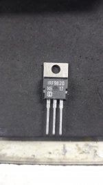
Sorry for the first post in Portuguese. I couldn't find the brand of these mosfets.
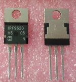
I thought they were harris, at first. They don't look like generic Chinese. But the Harris are these.
But now, looking closely, I see that they have the same design as the Harris and are not similar to other brands.
I thought they were harris, at first. They don't look like generic Chinese. But the Harris are these.
But now, looking closely, I see that they have the same design as the Harris and are not similar to other brands.
Attachments
Last edited:
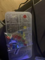
So since I gutted the old board to move the components over to a new I realised something, I won't be able to re-use the diodes because I can remember the polarity of them and have no way to check them. Now I have a bunch of these laying around the bag is from an Arduino kit and the box is from wish which would you guys think is the safer bet to use?
also related to this, how heat sensitive are the voltage regulators?
they where a pain too desolder with the heat sinks attached.
also related to this, how heat sensitive are the voltage regulators?
they where a pain too desolder with the heat sinks attached.
Attachments

Most multimeters can test a led, if I am not mistaken. Also, a very simple led and resistor circuit to test them with any wall-type PSU would be simple to create. I’m sure others will have more pointers, but lighting up a led is really simple to do. You could do it with the Arduino you already have, but a breadboard would be simpler, I think.…I won't be able to re-use the diodes because I can remember the polarity of them and have no way to check them...
Maybe I’m missing something,
Rafa.
I was getting horrible distortion out of my Whammy and found that the wiring scheme was the culprit. I had connected the Whammy to the output of the stereo/mono/mute switch, and the heavy distortion was present even with all downstream components powered off. It's now connected to the output of the source selector, and with the next switch on mute the Whammy is disconnected from everything.
I guess the Muses volume control, even when powered off, was interacting with and boosting the source signal. Maybe caps were charging up?

I guess the Muses volume control, even when powered off, was interacting with and boosting the source signal. Maybe caps were charging up?
Test with 9V battery + resistor (nom 1K)
You can also identify the polarity of an LED by inspecting the internal elements, use a magnifier if you need to.

I just plug em into my Mega328 component tester and hit the button. Presto, the display tells me which lead is (+) and which is (-). The Mega328 is also quite useful to get the correct pinout of 3-terminal BJTs, JFETs, and MOSFETs. And it'll measure resistance and also capacitance, when the color bands are ambiguous or the printed values are small & confusing.
_
_
- Home
- Amplifiers
- Pass Labs
- "WHAMMY" Pass DIY headphone amp guide