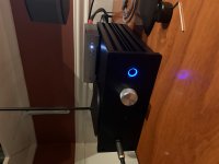
Finished my Whammy. I likes it. I'm surprised at the gainz, and it's dead silent.
I'm going from a DAC (topping d90, arrived today) into the whammy into an F6 and it's much louder than it was with the focusrite scarlett I was using as combo dac+pre before. I'm using the RC4580 chip right now and I have an LM833 and a MUSES01 to swap in as experiments. I went with 15V rails for a wide compatibility with many op-amps.
I'm considering adding a switch to flip between high-gain and low-gain modes by connecting different R values for R4/R8 to it. I'm wondering if that's the kind of thing you can do while it's running or if you need to turn the unit off first.
") At first read I thought you meant make the modification without turning off the Whammy. I thought to myself that you better be standing on a rubber mat.
At first read I thought you meant make the modification without turning off the Whammy. I thought to myself that you better be standing on a rubber mat.You should be able to switch from high to low or low to high on the fly. It's less of a change than throwing the on-off switch. But then I'm no EE and it's your gear.
You should be able to switch from high to low or low to high on the fly. It's less of a change than throwing the on-off switch. But then I'm no EE and it's your gear.
I'm teaching the neighbor kid how to solder. He won't know any better. This should be hilarious.
But seriously, if it melts I'll just build another one.
Does the bypass cap for the optocoupler affect the noise floor? I just built a 2nd whammy and it has a loud white hiss. The only deviation from the schematic is c13 and here i used a 2.2uf elcap (correct polarity) instead of 0.1uf film. well, also the gain resistor values are slightly lower- 2.2k and 800ohm but i dont think that should cause any issue?
It can do both.
Try small values.
Don't solder them just touch the cap leads across the resistor leads while looking at the square wave response.
Once you find the cap value that gives you the response you like then solder in.
Exactly what I was going to suggest - or clip on some clip leads and experiment . The values specified generally work for any OpAmps in the loop, but YMMV depending on the specific one you choose for your liking. I've done this also with different types/brands of caps and not only measured but listened to the results.
Speaking of optocouplers, what exactly is the difference between the white and black package optocouplers? I didn't think there was a difference, but I have learned since that the specifications are usually different. I used white package in my whammy and never had an issue, but would like to know.
Another finished Whammy!
Hey all!
Thanks again for all of the assist on this.. Thanks to 6l6 for the great instructions, Wayne for the design, pFarrell for being a great friend and helping me endlessly.. 2 picoDumbs, and avdesignguru for stepping in with some suggestions and tech support!
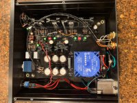
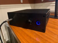
Overall, I'm really happy with the finished product! Had a buddy with a drill press and a lot of patience help me with cutting the holes in the galaxy 2U case. The Whammy is perfectly quiet, no hums or noises.. The only 'janky' part was that I didn't recess the volume knob fully enough and couldn't get the nut on the POT.. So I had to run a ground strap to the rear.. I tried to solder the ground wire to the front face of the pot, but it was taking so much heat, I was worried it would damage the POT.. So don't look to closely.. lol.. not proud of my solution, but it works for now..
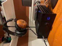
I"m listening via Tidal/iMac -> Modi Multibit --> Whammy -> Fostex TH-X00's
My first HiFi experience, and very happy!
PS.. swapped out black vol knob for the silver one.. much bettah..
Hey all!
Thanks again for all of the assist on this.. Thanks to 6l6 for the great instructions, Wayne for the design, pFarrell for being a great friend and helping me endlessly.. 2 picoDumbs, and avdesignguru for stepping in with some suggestions and tech support!
Overall, I'm really happy with the finished product! Had a buddy with a drill press and a lot of patience help me with cutting the holes in the galaxy 2U case. The Whammy is perfectly quiet, no hums or noises.. The only 'janky' part was that I didn't recess the volume knob fully enough and couldn't get the nut on the POT.. So I had to run a ground strap to the rear.. I tried to solder the ground wire to the front face of the pot, but it was taking so much heat, I was worried it would damage the POT.. So don't look to closely.. lol.. not proud of my solution, but it works for now..
I"m listening via Tidal/iMac -> Modi Multibit --> Whammy -> Fostex TH-X00's
My first HiFi experience, and very happy!
PS.. swapped out black vol knob for the silver one.. much bettah..
Attachments
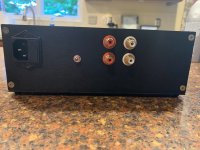
SkyPirate, it looks like you found the same solution I did for the LED power: the pads on R9 and R10.
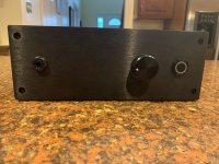
What did you use for the power switch? It looks great!
Did you wire it for pre-amp output with a switched jack?
Overall, very nice job!
rikiheck,
Thanks for the kind words.. I def leaned on a bunch of folks with it. I did use a switching jack and wired for pre-amp.. I don't know if I'll ever use it for one (pfarrell trying to talk me into building power amp).. but just in case!
As far as the switch goes, I used the rec in this thread somewhere..
APIELE [3 Year Warranty] 19mm Latching Push Button Switch 12V DC Angel Eye Halo Ring LED Metal 0.74" 1NO1NC SPDT with Wire Socket Plug (Blue LED/Black Shell): Amazon.com: Industrial & Scientific
It worked very well.. Came with a cannon type plug that's pre-wired but I didn't want all of that bulk in the case, so i just connected my wires direct to the spade terminals with female spade connects..
Thanks again!
john
Just a note: When I ordered the APIELE switch, it came with a spec sheet not shown on Amazon's website that rates the switch contacts at 250V 5A. They also offer 5A and 10A in 22mm versions. I have not tried the 10A version but both the 19mm and the 22mm 5A versions have been reliable in my projects.
I suspect that these switches do not carry a official safety rating from UL, CE or any other agency, thus the contact voltage rating cannot be listed on Amazon. If that is important to you, Mouser has E-Switch brand versions for about 50% more (in stainless finish) or you can go with the granddaddy maker of this switch type, Bulgin, for about 2X the cost.
I suspect that these switches do not carry a official safety rating from UL, CE or any other agency, thus the contact voltage rating cannot be listed on Amazon. If that is important to you, Mouser has E-Switch brand versions for about 50% more (in stainless finish) or you can go with the granddaddy maker of this switch type, Bulgin, for about 2X the cost.
Hi Pico, Just a quick note to say thankyou, yes a 30pf sorted out the slight spike on the 20k sq wave (C2 , C7), glad to read you've bought a PCB you're gonna love playing with it. I finally fitted a V6 Vivid in the op amp and what can I say, no more op amp messing around thats it done, beat that if you can world, needless to say it sounds fantastic easily up there with a £1500 headphone amp ( I know coz iv'e tried it!). I think I might build another.


It is definitely in the queue after the premium parts build of the Whammy I am doing now. Like yours, I too plan on using the Whammy's supply which makes the rest of the build a continuation of that by almost just swapping out the main board for the line stage boards + the short PSU board. Those three with the Galaxy II chassis smells like a new diyaudio kit that I'd be down with helping put together.
So on a whim i took out the opamp and connected the input straight to the 47ohm leading into the mosfet buffer and much to my surprise i quite like the sound. Its very open and smooth but i feel like its missing a lot of the impact it had when the opamp was in place. The mosfets im using for my nuild are irf530/9530 with 100ma(!) bias.
Is the lack of impact due to transconductance/input impedance? Im also using 10k ohm volume since my source is a ss output dac.
Is the lack of impact due to transconductance/input impedance? Im also using 10k ohm volume since my source is a ss output dac.
Are you using the same pot?
Well one thing is certainly different, you have a higher output impedance feeding into the mosfets. Not sure if that would be responsible for it.
The other thing that is certainly different is your damping factor at amp output is much lower (much higher output impedance)
Did you check dc offset?
It might not be zero without the opamp in the circuit.
Last edited:
- Home
- Amplifiers
- Pass Labs
- "WHAMMY" Pass DIY headphone amp guide