Looks like your HP output jack ground is not isolated. Can't see if the RCAs are either. Could be picking up noise directly from the AC line ground.
Is this because his/her output jack appears to only have the left/right channels and expects to have its ground terminal in contact with a chassis?
Also, ideally, would we want to have that nut and ground terminal in the back next to the RCAs in contact with the chassis as well? Basically, would it be even better if that paint is scratched away in that area?
Just curious and trying to learn through osmosis.
")
The headphone jack has all three, R, L, GND.
The jack and the RCAs should be isolated from the chassis. That way you can control the grounds to the chassis as opposed to having a bunch all over.
The chassis panels needs good conductivity to themselves, and the potentiometer body should be in contact with the bare chassis, and the body is more like chassis than ground.
The low noise configuration that works for me is using RCA and 1/4" jacks with isolated grounds connected to PCB circuit ground. AC line ground connected only to chassis ground. Only connection between circuit ground and chassis ground is via an RF bypass capacitor connected from isolated RCA input grounds to chassis ground.
Ahhh. Yes, that explains the recommendation for the RF bypass capacitor then.
Out of curiosity, why does having isolated grounds offer better noise levels as opposed to sharing one common ground with everything? Wouldn't you then need to worry about ground loops?
I'm guessing the idea here is to use the ground coming from the input ground as the "signal ground", and trying to isolate the other grounds from this signal ground as a means of preventing ground loops?
Simple solution that didn't cross my mind. Thanks!
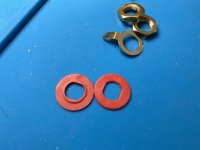
And also pay close attention to the plastic washers. If you look closely at the first picture of the washers, you'll see that there are 2 types: one with an inner ring that is supposed to slip into the hole that goes through the chassis and helps center the jack in the hole so it doesn't make contact. But it only goes into the hole one way so that it sits in the inner diameter of the hole without making contact with the sides. The other one is a plain old flat plastic washer. I don't know why they don't include 2 with the guide bushing but no one asked me.
Also don't mix them up with the two inputs - each RCA comes as a set containing one of each!I deformed one of mine debugging my grounding issue as I was re-installing it a few times, and let them touch at one point, so pay careful attention to it being inserted properly or you will connect the RCA's negative to the chassis.
You can always confirm your setup by checking that there is no continuity from the negative sleeve of the RCAs to the chassis, and only through the cap to the chassis star ground point on the other side.
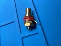
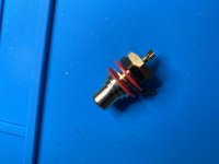
One other heads up on the RCA connectors is that they are shipped in a way that if installed in reverse order, definitely connects the negative to the chassis. I took a snap of the raw connectors as shipped, and you will notice the order that has the negative ring sandwiched between the two plastic washers. For this project you should have them setup the way I show in the last picture, which is to say, the plastic washers only make contact with the chassis, and the the negative ring on the outside of the last washer. This isolates the negative/barrel of the connector from the chassis. Again check for a lack of continuity to the chassis to confirm.
Attachments
Looks like your HP output jack ground is not isolated. Can't see if the RCAs are either. Could be picking up noise directly from the AC line ground.
HP jack is not - will be replacing it with a Nutrik but will wrap some e-tape on it temporarily and see if that improves things. Thanks!
And also pay close attention to the plastic washers....
Yup - those are correct. I've done a few other kits so I'm used to how those mount. Thanks!
The chassis really isn't that important in the big picture but it should be floating from your signal grounds at the signal inputs and outputs. That means your RCA inputs are isolated from the chassis with plastic washers or bushings and your headphone jack's common between right and left should not have any connection at the chassis. That means that a bunch of the popular 1/4" tip-ring-sleeve jacks will not work for this. If you have a chassis (I'm still holding out for a good one with mine mounted out in the open on plywood) you should bond the power cord's ground directly to the chassis. Wisdom holds that your reference ground point on the Whammy (or any other kind of audio device you build) should have low impedance at high frequencies (like a 0.01 uF capacitor direct connected) and higher impedance at low frequencies like a CL 60 or similar or a 10 Ohm resistor also direct connected. There are several examples of circuits that also use diodes back to back in parallel with these.
YouAgain, do you have a capacitor between your AC ground and input ground atm? I'm also waiting on a chassis but I soldered a cap between these and felt like it's caused more issues than solved. And that might explain why if the cap is only there for RF purposes to prevent ground loop noises to the chassis ground. Do I have that right?
YouAgain, do you have a capacitor between your AC ground and input ground atm? I'm also waiting on a chassis but I soldered a cap between these and felt like it's caused more issues than solved. And that might explain why if the cap is only there for RF purposes to prevent ground loop noises to the chassis ground. Do I have that right?
No, my AC feed is devoid of a ground conductor at this point. My input and output connectors are at the ends of cables going to the Whammy. The only important connection to ground is the potentiometer shaft connecting to board ground by a single wire. It is silent like this.
If you don't have a metal chassis there is really no reason to connect the AC ground to the circuit. The whole idea of that is to prevent you from getting a shock if there is some kind of short from AC mains to metal chassis. If there is nothing metal to fault to there is no need to protect yourself.
Of course when we put it into a chassis we will play by those rules and the added complexity of the ground path.
Attachments
No, my AC feed is devoid of a ground conductor at this point. My input and output connectors are at the ends of cables going to the Whammy. The only important connection to ground is the potentiometer shaft connecting to board ground by a single wire. It is silent like this.
I just gave this a shot and it's now dead quiet, even with the OPA1612.
About that chassis tho...

I just gave this a shot and it's now dead quiet, even with the OPA1612.
About that chassis tho...
Great that it worked for you. And my amp wasn't built to look at! Not yet at least.
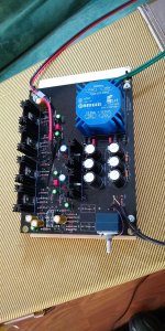
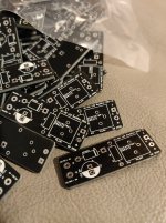
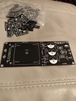
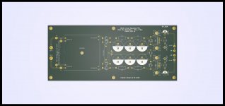
Hey guys. I have been getting handy with KiCad just lately and made a few power supply PCB designs based on the one on the Whammy and I also made a PCB of the circuit 6L6 posted which provides a rectifier to drive an LED for power on indicator.
I got some boards made of the single rail positive power supply and the LED rectifier and I am just awaiting the components from Mouser so I can build some for testing.
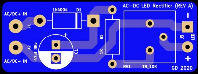
I made an alteration to the schematic 6L6 posted on the rectifier and made the addition of a 10K trim pot so you can adjust the brightness of the power LED on the fly.
These designs aren't just useful for the Whammy but can be useful for many other future projects.
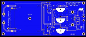
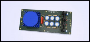
I also did two types of the dual rail PCB. One with a positive and negative supply which is pictured and the other which is dual positive which is useful for building standalone linear power supply boxes.
Let me know what you guys think.
I got some boards made of the single rail positive power supply and the LED rectifier and I am just awaiting the components from Mouser so I can build some for testing.
I made an alteration to the schematic 6L6 posted on the rectifier and made the addition of a 10K trim pot so you can adjust the brightness of the power LED on the fly.
These designs aren't just useful for the Whammy but can be useful for many other future projects.
I also did two types of the dual rail PCB. One with a positive and negative supply which is pictured and the other which is dual positive which is useful for building standalone linear power supply boxes.
Let me know what you guys think.
Attachments
Absolutely fantastic!! Well done!!
Those rectifier boards are tiny! Can easily hide them in heat shrink tubing or mount on the inside of the front panel with some double sided foam pads.
- Home
- Amplifiers
- Pass Labs
- "WHAMMY" Pass DIY headphone amp guide