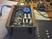

I just finished my Whammy, uniquely used as HPA at the moment.
I am already very happy with the performances. It sounds much better than the JDS Atom I was using so far.
My configuration is:

I went with:
So far, I measured few points (currently testing OPA2107), and got:
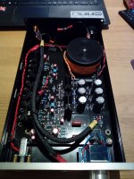
I could not get the RCAs mounted on chassis without the outer contact touching the grounded panel. I'll try to insulate the RCA and connect it to the ground via a cap as suggested.
Question: For which Op Amp would you recommend using the feedback compensation cap C2/C7?
I'll now start playing around with Bias and Op Amps. (only tested LM833N and OPA2107 so far).
Thanks again!
I am already very happy with the performances. It sounds much better than the JDS Atom I was using so far.
My configuration is:
- Foobar -> Schiit Bifrost MB -> Whammy HPA -> 4.5mm modded HD58X
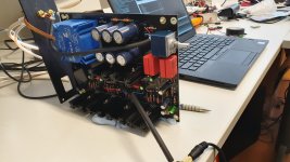
I went with:
- IRF9610PBF/IRF610PBF Output transistors
- Taller and cheaper heatsinks "Aavid 531202B02500G" (38->51mm height)
- Pana FC capacitors for decoupling
- 2xWima MKP10 250Vac 0.68uF for coupling on C1/C5
- MC79(8)15ACTG regulators + Diode configuration
- Chassis Hifi 2000 Galaxy GX283 (80x230x230)
- Various Op Amps:
- OPA2156
- OPA2107AU
- OPA1642
- LME49860MAX/NOPB
- LME49720NA/NOPB
- LM883N
- AD8599ARZ
So far, I measured few points (currently testing OPA2107), and got:
- 0.645V across R37 (126mA drained on each rails, with 10ohms output bias resistors)
- 1.4mV DC output
- 0.9mV DC across coupling caps C26/C27
- Nice regulation on the CRCRC network: DC(AC): 33.9V(85mV) / 33.26V(8mV) / 32.64V(1.6mV)
- LED voltage sits at 1.74V
I could not get the RCAs mounted on chassis without the outer contact touching the grounded panel. I'll try to insulate the RCA and connect it to the ground via a cap as suggested.
Question: For which Op Amp would you recommend using the feedback compensation cap C2/C7?
I'll now start playing around with Bias and Op Amps. (only tested LM833N and OPA2107 so far).
Thanks again!
Attachments
I went all the way up to a AD812 and failed to coax out oscillation without the feedback compensation capacitors, so honestly, I think it's unnecessary.Question: For which Op Amp would you recommend using the feedback compensation cap C2/C7?
Did somebody try with the discrete Burson op amps?
I ordered the Classic V6 dual version so will see when time comes. The first try will be with OPA2604 or the supplied op amp in the kit.
Test of PSU will probably be tomorrow. Soldered it this night.
I can see many use a 3 wire cable from PCB RCA out to RCA connectors. I think it could give crosstalk and also no good to let the cable pass close to the trafo/PSU. I am thinking of let the long side be the front so there is short distance to RCA connectors.
I played around with this idea and even made the case to fit the PCB both ways so that I could decide and try things out.Did somebody try with the discrete Burson op amps?
I ordered the Classic V6 dual version so will see when time comes. The first try will be with OPA2604 or the supplied op amp in the kit.
Test of PSU will probably be tomorrow. Soldered it this night.
I can see many use a 3 wire cable from PCB RCA out to RCA connectors. I think it could give crosstalk and also no good to let the cable pass close to the trafo/PSU. I am thinking of let the long side be the front so there is short distance to RCA connectors.
I loved to have short distance between the RCA inputs and the audio in, but then the potentiometer would have ended with long cable so to the front. I decided that was the "greater evil" of the two and went with the standard orientation but moved the RCA inputs to the opposite corner as the trafo.
I can dig the photos tomorrow or you can fish them in this thread if you want a more graphically visual example to what I am describing.
If you do go sideways, I'd be interested in your results!
Best,
Rafa.
Yes, I meant RCA in.....of course. I had RCA out also in my mind when writing the first post.
Yes, pot must be mounted on long side of chassis so wires will be a bit longer compared to direct PCB mount….unless you are happy with pot out of the side of the chassis
But at least twist of L and R channel input should be avoided and away from the power transformer.
Yes, pot must be mounted on long side of chassis so wires will be a bit longer compared to direct PCB mount….unless you are happy with pot out of the side of the chassis
But at least twist of L and R channel input should be avoided and away from the power transformer.
If we look at the official Pass Lab headphone amp we see very short distance from RCA in/out and a flat cable from pot to PCB but long away from power transformer:
Pass Labs HPA-1 headphone amplifier | Stereophile.com
…….maybe using a discrete Burson opamp it can compete with the HPA-1 …..but the power supply in HPA-1 looks a bit "stronger"......and trafo has some shielding we don't have in Whammy…...
Pass Labs HPA-1 headphone amplifier | Stereophile.com
…….maybe using a discrete Burson opamp it can compete with the HPA-1
…..but the power supply in HPA-1 looks a bit "stronger"......and trafo has some shielding we don't have in Whammy…...
Last edited:
Sounds good…..but I think I will try to do it as "theoretical" good as possible with short signal wires etc. and maybe also mu-metal shielding of the kit-trafo…..because I have mu-metal sheets I used for M2X Edcor trafo.
Is there any reason I should not use the "standard" 10 ohm NTC resistor from signal ground to chassis like I do in other build which works fine.....instead of the supplied cap in the kit?
Also I wait to install the two 220uF caps close to opamp socket until I get the Burson V6 opamp to check how much space I need. I may also go for 5 ohm "bias" resistors.....
PSU worked fine......I tested it this morning.
Whammy use "optical" bias......HPA-1 not.....as far as I can see. Also Whammy does not need DC-servo. I may omit input caps if I measure no DC out of my DAC...….
In some ways Whammy is "more Pass" than HPA-1...…?
I use 2x22V kit trafo…..and I think I read in a previous post someone which did it.....but not 100% sure which trafo he used…..but the heatsink of the regulator went up to about 55 C. Then Wayne later responded that he has run the regulators for one year at 100 C without problems. But if I exceed the limit power of the trafo then it is a "no go".....
If we say 250 mA and 50V.....to have easy values…...that is 12.5 VA. Trafo is 2 x 12.5 VA but need some margin and we have the peak current from bridge etc...….but should be possible? …..we will see 10 or 8 or 6 ohm would also be fine.....
If we say 250 mA and 50V.....to have easy values…...that is 12.5 VA. Trafo is 2 x 12.5 VA but need some margin and we have the peak current from bridge etc...….but should be possible? …..we will see 10 or 8 or 6 ohm would also be fine.....
Also. the transformer is in a plastic capsul.
Do not mix up theatsink temperature with device die temperature.
With 2x22V transformer. and 15V regulators (without the LED's), the regulators must burn off just as much Power as the all of the output transistors combined.
Do not mix up theatsink temperature with device die temperature.
With 2x22V transformer. and 15V regulators (without the LED's), the regulators must burn off just as much Power as the all of the output transistors combined.
Last edited:
- Home
- Amplifiers
- Pass Labs
- "WHAMMY" Pass DIY headphone amp guide