Interested in possibly using my whammy as a preamp, was wondering a couple of things:
Do I need to switch the ground as well as the signal lines? I assume so, to keep noise from downstream components coming back into the signal path. What switch should I use for this? Are there any other considerations I need to take into account before using this project as a preamp?
Do I need to switch the ground as well as the signal lines? I assume so, to keep noise from downstream components coming back into the signal path. What switch should I use for this? Are there any other considerations I need to take into account before using this project as a preamp?
Hello...I just finished building my Whammy and it was working and sounding great, and was super fun to build. The last step I had was to try and add a front panel LED.
However while trying to test my LED, I accidentally shorted the anode of D4 to the cathode of C28. The connection was very brief but there was a whiff of smoke from what looked like U2 7915 (or at least that area). The D6 LED sputtered and turned off. My voltage test between R13 and R14 had been -16.9, now it's -32.
*sigh* what have I done? Do I just need to replace U2? rebuild the PSU? Please help! I think the worst feeling in DIY is to have a finished, beautiful project, then f*** it up for no good reason.
oh, and while it's less important at the moment, can someone give some specific instructions for adding a front panel LED? with the actual pads to use, etc? I've searched the thread but all I can find is a circuit diagram and "run it off the secondary." I've built a ton of stuff but my actual electronics knowledge is (obviously) not up to the task.
oh, and while it's less important at the moment, can someone give some specific instructions for adding a front panel LED? with the actual pads to use, etc? I've searched the thread but all I can find is a circuit diagram and "run it off the secondary." I've built a ton of stuff but my actual electronics knowledge is (obviously) not up to the task.
Note: the following is based on using LED referencing of the regulators, where you do not stuff or solder resistors R9 and R10 on the PCB.
Solder one end of your LED dropping resistor into the +15 end of the unused position for component R10 (the end towards the front of the PCB). Air wire the free end of the resistor to the anode of the "Power On" LED.
Connect the cathode of the "Power On" LED to the unused grounded side of the component position for component R9 (again, the end towards the front of the PCB).
Attachments
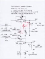
Note: the following is based on using LED referencing of the regulators, where you do not stuff or solder resistors R9 and R10 on the PCB.
Solder one end of your LED dropping resistor into the +15 end of the unused position for component R10 (the end towards the front of the PCB). Air wire the free end of the resistor to the anode of the "Power On" LED.
Connect the cathode of the "Power On" LED to the unused grounded side of the component position for component R9 (again, the end towards the front of the PCB).
Thank you, exactly what I was looking for.
Hello...I just finished building my Whammy and it was working and sounding great, and was super fun to build. The last step I had was to try and add a front panel LED.
However while trying to test my LED, I accidentally shorted the anode of D4 to the cathode of C28. The connection was very brief but there was a whiff of smoke from what looked like U2 7915 (or at least that area). The D6 LED sputtered and turned off. My voltage test between R13 and R14 had been -16.9, now it's -32.
*sigh* what have I done? Do I just need to replace U2? rebuild the PSU? Please help! I think the worst feeling in DIY is to have a finished, beautiful project, then f*** it up for no good reason.
Trying to puzzle this out a little further, based on my limited knowledge. I apparently fried the regulator of the negative rail. Does that mean components downstream were potentially exposed to more power than they are rated for, potentially frying them as well? Or does the LED act as a sacrificial diode, so when it got overloaded and died, power did not pass beyond the PSU?
I'm planning an order from Mouser for another regulator and hoping to get that out ASAP...I'm hoping I didn't fry any MOSFETs or anything else too..
Last edited:
Trying to puzzle this out a little further, based on my limited knowledge. I apparently fried the regulator of the negative rail. Does that mean components downstream were potentially exposed to more power than they are rated for, potentially frying them as well? Or does the LED act as a sacrificial diode, so when it got overloaded and died, power did not pass beyond the PSU?
I'm planning an order from Mouser for another regulator and hoping to get that out ASAP...I'm hoping I didn't fry any MOSFETs or anything else too..
If D6 is dead (open circuit), or installed backwards, there will be no regulation reference and the output of U2 will go to the full raw supply voltage. It's pretty hard to kill U2. My guess is D6 is fried.
BTW, a good investment for testing transistors and diodes is a mega 328 tester. It will also show a schematic of a functioning device with marked pinouts on screen. It's inexpensive, and available with or without a plastic enclosure.
Aideepen Mega328 LCR-T4 Transistor Tester Diode Triode Capacitance LCR ESR Meter Module MOS PNP/NPN M328 (Battery Buckle): Amazon.com: Industrial & Scientific
LCR-T4 Mega328 Transistor Tester Diode Triode Capacitance ESR Meter W/ Shell US 6630597742690 | eBay
Last edited:
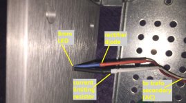
In one of my recent builds I decided I wanted a power indicator LED that stopped glowing the very instant I turned off the power switch. The DC supply rails don't bleed down to zero for many seconds, so I couldn't connect my "pilot light" there; it would remain ON for a long time after the power was switched OFF.
I connected it to the transformer secondary (AC voltage) because that DOES instantly drop to zero when the mains power is switched off. A series diode was installed to prevent the LED from entering reverse breakdown. The diode means I'm applying half wave rectified pulses to the LED, and relying upon persistence of vision to give the perception that this 60 Hertz flickering LED, appears to emit a continuous unchanging beam of light.
The rectifier diode is a 1N3595 because I've got a drawer full of them; they are small and have very low reverse leakage current, so the LED is very well protected. Probably a 1N4148 would have worked well enough. The LED is a wide viewing angle (112 deg) blue diode whose brightness rating is pretty high: 5000 mcd. So I'm running it at about 1 milliamp of RMS current.
_
Attachments
If D6 is dead (open circuit), or installed backwards, there will be no regulation reference and the output of U2 will go to the full raw supply voltage. It's pretty hard to kill U2. My guess is D6 is fried.
BTW, a good investment for testing transistors and diodes is a mega 328 tester. It will also show a schematic of a functioning device with marked pinouts on screen. It's inexpensive, and available with or without a plastic enclosure.
Aideepen Mega328 LCR-T4 Transistor Tester Diode Triode Capacitance LCR ESR Meter Module MOS PNP/NPN M328 (Battery Buckle): Amazon.com: Industrial & Scientific
LCR-T4 Mega328 Transistor Tester Diode Triode Capacitance ESR Meter W/ Shell US 6630597742690 | eBay
Thanks, I've been meaning to get one of those testers anyway since I build a lot of guitar pedals, which often work best with transistors of certain hFe and leakage, etc.
The U2 regulator is only 56 cents, so I'll order one just in case along with new LEDs. Just so I'm clear, if U2 is outputting the full raw supply voltage, does that endanger any other components, or no?
In one of my recent builds I decided I wanted a power indicator LED that stopped glowing the very instant I turned off the power switch. The DC supply rails don't bleed down to zero for many seconds, so I couldn't connect my "pilot light" there; it would remain ON for a long time after the power was switched OFF.
I connected it to the transformer secondary (AC voltage) because that DOES instantly drop to zero when the mains power is switched off. A series diode was installed to prevent the LED from entering reverse breakdown. The diode means I'm applying half wave rectified pulses to the LED, and relying upon persistence of vision to give the perception that this 60 Hertz flickering LED, appears to emit a continuous unchanging beam of light.
The rectifier diode is a 1N3595 because I've got a drawer full of them; they are small and have very low reverse leakage current, so the LED is very well protected. Probably a 1N4148 would have worked well enough. The LED is a wide viewing angle (112 deg) blue diode whose brightness rating is pretty high: 5000 mcd. So I'm running it at about 1 milliamp of RMS current.
_
Great suggestion, Mark. I've got a few builds I may go back and change to this scheme. I too am bothered by the long bleed down.
Also If you look at the photo in my post 1525 you will see the diode glued into a small metal plate (I sometimes use hardwood). This is double side taped over a 1/16" hole inside the front panel. This allows me to use a 5mm diode and create a 1.5mm "stealth" indicator on the front panel.
Attachments
Thanks, I've been meaning to get one of those testers anyway since I build a lot of guitar pedals, which often work best with transistors of certain hFe and leakage, etc.
The U2 regulator is only 56 cents, so I'll order one just in case along with new LEDs. Just so I'm clear, if U2 is outputting the full raw supply voltage, does that endanger any other components, or no?
Theoretically, if you have exceeded rated voltages, yes. In practicality, if you did not apply a headphone load to the circuit and drive a signal through it, probably no damage was done. Maybe the opamp if it was installed. The optocouplers and mosfets are pretty tough.
Theoretically, if you have exceeded rated voltages, yes. In practicality, if you did not apply a headphone load to the circuit and drive a signal through it, probably no damage was done. Maybe the opamp if it was installed. The optocouplers and mosfets are pretty tough.
There was no source connected but the headphones may have been plugged in, I don't recall honestly. The opamp was installed but it wasn't my favorite and I've got others. Hopefully the damage is limited to the LED or U2.
Sometimes you gotta overnight parts from Mouser, and this was one such occasion. I replaced the regulator and LED in my Whammy, and voila, everything's working including the opamp. I also utilized Mark Johnson's front panel LED suggestion directly from the secondary (using a 1N4148) and it works like a charm. All is good, thanks Wayne for the amp, and everyone for their prompt assistance!
Okay guys I have spent quite a bit of time and money on obtaining OP Amps for testing and here are by findings:
Dual Op Amps (8P-DIP):
AD823ANZ:
Operating Voltage: 36v MAX
Slew Rate: 22v/µs
DC Offset: L 0.5mV / R -0.2mV
FET: Yes
Notes: Vocals very good but some mids and treble sounds a little raspy.
LM833-N:
Operating Voltage: 36v MAX
Slew Rate: 7v/µs
DC Offset: L -0.1mV / R 3.4mV
FET: No
Notes: Very good all round OP Amp with clear vocals, good soundstage and natural bass.
LM833P:
Operating Voltage: 36v MAX
Slew Rate: 7v/µs
DC Offset: L 22.9mV / R 26.2mV
FET: No
Notes: Very good OP Amp with clear vocals and good soundstage. Improved version of the LM833-N although DC offset is considerably higher.
RC4580 (Texas Instruments):
Operating Voltage: 18v MAX
Slew Rate: 5v/µs
DC Offset: L 14.2mV / R 14.1mV
FET: No
Notes: Good general OP Amp with tiny noticable distortion amounts with certain types of music, sounds best with dance music.
OPA2134PA SoundPlus:
Operating Voltage: 18v MAX
Slew Rate: 20v/µs
DC Offset: L 0.6mV / R 0.4mV
FET: Yes
Notes: Very clear with good soundstage and vocals very pronounced. Very nice OP Amp.
OPA2228PA
Operating Voltage: 18v MAX
Slew Rate: 2.3v/µs
DC Offset: L -0.2mV / R -0.1mV
FET: No
Notes: Very good, clear up front vocals, very good mid and treble, wide soundstage, overall I like this OP Amp.
OPA2107AP
Operating Voltage: 18v MAX
Slew Rate: 18v/µs
DC Offset: L -0.2mV / R -0.3mV
FET: Yes
Notes: Very clear and concise right through all the ranges. Vocals very prominent and wide soundstage. I really like this one.
LME49720NA
Operating Voltage: 17v MAX
Slew Rate: 20v/µs
DC Offset: L 0.8mV R 1.6mV
FET: No
Notes: Nice all round OP Amp with good soundstage. Very clear but mellow sounding.
AD746JNZ
Operating Voltage: 18v MAX
Slew Rate: 75v/µs
DC Offset: L -0.3mV / R -0.2mV
FET: Yes
Notes: Very nice sounding with wide soundstage, clear mids and treble with punchy bass. I really like this one.
LM4562NA:
Operating Voltage: 17v MAX
Slew Rate: 20mv/µs
DC Offset: L -0.4mV / R -1.1mV
FET: No
Notes: Very good all round OP Amp with clear vocals and good soundstage.
NJM4556AD:
Operating Voltage: 18v MAX
Slew Rate: 3v/µs
DC Offset: L 5.8mV / R 5.4mV
FET: No
Notes: Nice OP Amp with clear vocals, wide soundstage and balanced bass. Mids and trebles seem a little softer compared with other OP Amps.
Burson V6 Vivid Dual:
Operating Voltage: 33v MAX
Slew Rate: 45v/µs
DC Offset: L -2.0mV / R -1.5mV
FET: Yes (Fully Discrete)
Notes: Premium OP Amp obviously by far the best I've tried so far. Deep and wide reaching soundstage and up front clear vocals. My number one choice.
Next time I will be testing the following SOIC OP Amps on 8P-DIP adapters:
OPA1622, OPA1662, OPA2210, OPA2189 and OPA1692
Hope some of you find this helpful.")
Dual Op Amps (8P-DIP):
AD823ANZ:
Operating Voltage: 36v MAX
Slew Rate: 22v/µs
DC Offset: L 0.5mV / R -0.2mV
FET: Yes
Notes: Vocals very good but some mids and treble sounds a little raspy.
LM833-N:
Operating Voltage: 36v MAX
Slew Rate: 7v/µs
DC Offset: L -0.1mV / R 3.4mV
FET: No
Notes: Very good all round OP Amp with clear vocals, good soundstage and natural bass.
LM833P:
Operating Voltage: 36v MAX
Slew Rate: 7v/µs
DC Offset: L 22.9mV / R 26.2mV
FET: No
Notes: Very good OP Amp with clear vocals and good soundstage. Improved version of the LM833-N although DC offset is considerably higher.
RC4580 (Texas Instruments):
Operating Voltage: 18v MAX
Slew Rate: 5v/µs
DC Offset: L 14.2mV / R 14.1mV
FET: No
Notes: Good general OP Amp with tiny noticable distortion amounts with certain types of music, sounds best with dance music.
OPA2134PA SoundPlus:
Operating Voltage: 18v MAX
Slew Rate: 20v/µs
DC Offset: L 0.6mV / R 0.4mV
FET: Yes
Notes: Very clear with good soundstage and vocals very pronounced. Very nice OP Amp.
OPA2228PA
Operating Voltage: 18v MAX
Slew Rate: 2.3v/µs
DC Offset: L -0.2mV / R -0.1mV
FET: No
Notes: Very good, clear up front vocals, very good mid and treble, wide soundstage, overall I like this OP Amp.
OPA2107AP
Operating Voltage: 18v MAX
Slew Rate: 18v/µs
DC Offset: L -0.2mV / R -0.3mV
FET: Yes
Notes: Very clear and concise right through all the ranges. Vocals very prominent and wide soundstage. I really like this one.
LME49720NA
Operating Voltage: 17v MAX
Slew Rate: 20v/µs
DC Offset: L 0.8mV R 1.6mV
FET: No
Notes: Nice all round OP Amp with good soundstage. Very clear but mellow sounding.
AD746JNZ
Operating Voltage: 18v MAX
Slew Rate: 75v/µs
DC Offset: L -0.3mV / R -0.2mV
FET: Yes
Notes: Very nice sounding with wide soundstage, clear mids and treble with punchy bass. I really like this one.
LM4562NA:
Operating Voltage: 17v MAX
Slew Rate: 20mv/µs
DC Offset: L -0.4mV / R -1.1mV
FET: No
Notes: Very good all round OP Amp with clear vocals and good soundstage.
NJM4556AD:
Operating Voltage: 18v MAX
Slew Rate: 3v/µs
DC Offset: L 5.8mV / R 5.4mV
FET: No
Notes: Nice OP Amp with clear vocals, wide soundstage and balanced bass. Mids and trebles seem a little softer compared with other OP Amps.
Burson V6 Vivid Dual:
Operating Voltage: 33v MAX
Slew Rate: 45v/µs
DC Offset: L -2.0mV / R -1.5mV
FET: Yes (Fully Discrete)
Notes: Premium OP Amp obviously by far the best I've tried so far. Deep and wide reaching soundstage and up front clear vocals. My number one choice.
Next time I will be testing the following SOIC OP Amps on 8P-DIP adapters:
OPA1622, OPA1662, OPA2210, OPA2189 and OPA1692
Hope some of you find this helpful.
- Home
- Amplifiers
- Pass Labs
- "WHAMMY" Pass DIY headphone amp guide