My Whammy build
I finally finished this build yesterday, but firstly I have to thank Wayne for an excellent DIY project.
I have been running this PCB in my garage for about 300h, so it should have settled by now. My first initial impressions from today are that this amp is really good. What especially stands out is the extremely natural mid range. Lower and upper frequencies are also very good.
The OPA2604 sounds really good, surprising because this op-amp does not sound good in any of my other amps or DACs (very dark sound).
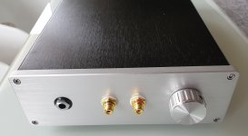
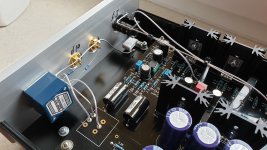
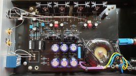
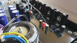
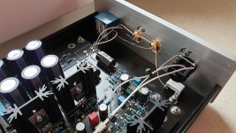
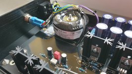
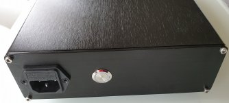
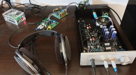
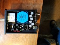
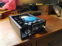
I am very satisfied with the build, especially the wiring turned out nice (using a 1,3mm diameter silver coated solid copper wire for the grounding) , box looks elegant.
My Specification: Polish toroidial transformer 30VA 2x18v with shield, Voltage after regulators +/-17V, Fairchild FQP3N30 / FQP3P20, OPA2604, Miflex PP 1uF caps, Ali express case
Listening setup: Raspberry pi3b running picoreplayer, DAC modded Chinese ES9038Q2M with muses02 opamp, headphones Sennheiser HD650
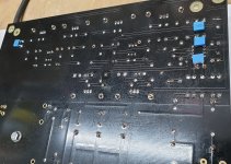
Mods: not much, just some extra 100nF filtering caps on the other side.
Some build issues: I had some problems getting a symmetrical voltage when using LEDs for the regulators, I fixed this by removing the LEDs and putting modified values for R9/R10 R13/R14, I also needed to put 150pF for CX otherwise the amp was not stable.
Output offset voltage is now approx 10mV, The muses02 has a lower offset Voltage but I am using it in the DAC.
Future planned mods, I have ordered more muses02 op-amps, this amp is amazing in the DAC, also in a LME49600 headphone amp. In the future I will try doing a blind test comparing three other headphone amps.
here are some pictures:
I finally finished this build yesterday, but firstly I have to thank Wayne for an excellent DIY project.
I have been running this PCB in my garage for about 300h, so it should have settled by now. My first initial impressions from today are that this amp is really good. What especially stands out is the extremely natural mid range. Lower and upper frequencies are also very good.
The OPA2604 sounds really good, surprising because this op-amp does not sound good in any of my other amps or DACs (very dark sound).
I am very satisfied with the build, especially the wiring turned out nice (using a 1,3mm diameter silver coated solid copper wire for the grounding) , box looks elegant.
My Specification: Polish toroidial transformer 30VA 2x18v with shield, Voltage after regulators +/-17V, Fairchild FQP3N30 / FQP3P20, OPA2604, Miflex PP 1uF caps, Ali express case
Listening setup: Raspberry pi3b running picoreplayer, DAC modded Chinese ES9038Q2M with muses02 opamp, headphones Sennheiser HD650
Mods: not much, just some extra 100nF filtering caps on the other side.
Some build issues: I had some problems getting a symmetrical voltage when using LEDs for the regulators, I fixed this by removing the LEDs and putting modified values for R9/R10 R13/R14, I also needed to put 150pF for CX otherwise the amp was not stable.
Output offset voltage is now approx 10mV, The muses02 has a lower offset Voltage but I am using it in the DAC.
Future planned mods, I have ordered more muses02 op-amps, this amp is amazing in the DAC, also in a LME49600 headphone amp. In the future I will try doing a blind test comparing three other headphone amps.
here are some pictures:
Attachments
-
 190310_Whammy_1.jpg224.5 KB · Views: 935
 -
 190310_Whammy_9.jpg405 KB · Views: 394
 -
 190310_Whammy_8.jpg543.8 KB · Views: 384
 -
 190310_Whammy_7.jpg618.3 KB · Views: 339
 -
 190310_Whammy_6.jpg418.5 KB · Views: 363
 -
 190310_Whammy_5.jpg409.5 KB · Views: 831
 -
 190310_Whammy_4.jpg447.6 KB · Views: 881
 -
 190310_Whammy_3.jpg241.5 KB · Views: 907
 -
 190310_Whammy_2.jpg449.6 KB · Views: 907
It's Alive!!
Another Whammy entered the world!
6L6's instructions were good and the Whammy worked from the moment it was turned on.
It's got about 50 hours on it now. It was rough at first and got smoother by 10 hours then started to really flesh out nicely as the hours rolled on.
It's setup as a preamp for the amp camp amp and early indications are the two are going to play nicely together.
Me happy.")
Many thanks to Wayne, 6l6, Jason and everyone else for making such nice things available to everyone. The combo has really exceeded my expectations.
Another Whammy entered the world!
6L6's instructions were good and the Whammy worked from the moment it was turned on.
It's got about 50 hours on it now. It was rough at first and got smoother by 10 hours then started to really flesh out nicely as the hours rolled on.
It's setup as a preamp for the amp camp amp and early indications are the two are going to play nicely together.
Me happy.
Many thanks to Wayne, 6l6, Jason and everyone else for making such nice things available to everyone. The combo has really exceeded my expectations.
It's a fun build and I think you'll be happy with the results.
Agree,
It is fun. I am building my second Whammy.. Just to build it!!
I might build a third one..
Hi guys, I am planning my Whammy build, and I was wondering how critical is the value of the gate resistor on the output MOSFETs? For whatever reason the 499R RN55D resistor is $1.28 at Mouser, whereas the 511R is $0.16. Small potatoes, but still would rather save where I can. But more broadly, what are the key design considerations to keep in mind here?
The Whammy is my first soldering project. So here is perhaps a simple question. A combination of Whammy with an integrated DAC is planned. However, I would like to keep the possibility to run the Whammy with and without DAC.
What should the wiring look like for this? Can the input of the Whammy PCB be double assigned with RCA-socket and DAC?

What should the wiring look like for this? Can the input of the Whammy PCB be double assigned with RCA-socket and DAC?
This value is not critical. The gate resistor along with input capacitance of mosfet form the low pass filter to prevent the high frequency oscillations.Hi guys, I am planning my Whammy build, and I was wondering how critical is the value of the gate resistor on the output MOSFETs? For whatever reason the 499R RN55D resistor is $1.28 at Mouser, whereas the 511R is $0.16. Small potatoes, but still would rather save where I can. But more broadly, what are the key design considerations to keep in mind here?
This value is not critical. The gate resistor along with input capacitance of mosfet form the low pass filter to prevent the high frequency oscillations.
Thanks for your reply. It seems like these oscillations typically manifest themselves north of 50 MHz, so a corner frequency 1 decade below that is maybe a good target (5 MHz corner to ensure -20 dB attenuation at 50 MHz). For the FQP3P20/FQP3N30, the minimum listed input capacitance is 175 pF, which suggests that a gate-stopper value of ~180R is maybe a good lower bound (-3 dB just north of 5 MHz). This is inline with the guidance in [this post], which suggests that gate-stopper values between 47-220R tend to have a minimal impact on sound quality.
An externally hosted image should be here but it was not working when we last tested it.
So I thought I was done with the basic build.. went n fired it up.. the 47R resistors (36 and 35) suddenly went boom... they caught smoke too.. any ideas?
p.s. I tested the power supply post building. Seemed ok. was getting around 17.5
Last edited:
WHAMMY variant
I posted some information in post #388 about my try to make a reduced size WHAMMY using surface mount components for much of the design and I may have followed up with some information about having a high frequency oscillation that subsequently got solved.
After working on the design for awhile and testing a FET switch based stepped attenuator I designed with the board I ended up not using the attenuator design.
I then did an iteration on the main board design to move to the Talema toroid transformer instead of the Hammond transformer I originally had in the design. I also added a DS1882 attenuator to the board for volume control. The attenuator is controlled by an MSP430FR2433 processor mounted on a small front panel along with a small OLED display.
The design includes a board mounted input jack and board mounted power input module. It all fits into a Hammond 1455 series chassis that's a smaller version of the original WHAMMY. And there are no wires.
A couple pictures showing the board in the enclosure and the front panel display.
Attachments
Those 47 Ohm resistors serve multiple purposes and letting you know your op amp is bad or miss stuffed is one.
I made a mistake
That's the OPA2156 converted to DIP8.. The white dot is where I was supposed to orient the SOIC op amp towards for soldering. I used the white dot yet again as a means of identifying orientation of op amp.. just put it facing the notch on the PCB.
It was supposed to be the other way around..
Currently waiting for the replacement resistors. They'll be here soon hopefully. I've measured the other resistors and they seem to still measure alright. Hopefully nothing else went bad.
I did have some SMD 47ohm resistors that I tried soldering using a solder bridge and for some reason I got really high DC between channels and ground.. (R36 when measured during running seemed to show much higher resistance like.. 80+ ohm.. 35 was still around 47.
The power supply stage still shows around 16V though.. Let's see if proper resistors fix this.
EDIT: I am currently using the RC4580 that came with the kit
I posted some information in post #388 about my try to make a reduced size WHAMMY using surface mount components for much of the design and I may have followed up with some information about having a high frequency oscillation that subsequently got solved.
After working on the design for awhile and testing a FET switch based stepped attenuator I designed with the board I ended up not using the attenuator design.
I then did an iteration on the main board design to move to the Talema toroid transformer instead of the Hammond transformer I originally had in the design. I also added a DS1882 attenuator to the board for volume control. The attenuator is controlled by an MSP430FR2433 processor mounted on a small front panel along with a small OLED display.
The design includes a board mounted input jack and board mounted power input module. It all fits into a Hammond 1455 series chassis that's a smaller version of the original WHAMMY. And there are no wires.
A couple pictures showing the board in the enclosure and the front panel display.
I love this.. Any chance you will make this board available?
Thanks
- Home
- Amplifiers
- Pass Labs
- "WHAMMY" Pass DIY headphone amp guide