How about a pure parts kit and a part & chassis kit? the pure parts kit could be the PCB parts only. So that if you buy a e-bay chassis (that often has Power switch, volume knob, IEC socket+++) you don't end up with twice the parts, that half of it can't be used and a higher bill.
How about a pure parts kit and a part & chassis kit? the pure parts kit could be the PCB parts only. So that if you buy a e-bay chassis (that often has Power switch, volume knob, IEC socket+++) you don't end up with twice the parts, that half of it can't be used and a higher bill.
Thanks for the suggestion. The intention is to offer a chassis in the very near future, then it's just kit + chassis = done.
The reason we don't offer sub-kits in general is that once the main product has sold out, you end up with a bunch of orphaned sub-kits. If the sub-kits sell out then you have people unhappy they can't build a full kit. If you don't do another run you're up the creek and left holding dead stock and it's all been for naught. There's also now twice as many SKUs to manage and restock and a cascade of unexpected supply chain synchronization issues inevitably ensue.
We've done our best for some other projects to make things as affordable as possible for DIYers, like making the ACA power supply independent of the kit, and offering the ACN with a separate chassis connector kit, but for now with the WHAMMY we'll just keep it simple, and in the future we may offer more options.
As Jim said, you can always use the connectors for another project.
Well, I pulled the trigger on this Parts kit! Lets see how things turn out... really excited to build this. Thanks Wayne, thanks 6L6 and thanks Jason!
I will be ordering some 'additional' OpAmps from Mouser.
Other than those, any suggestions of things I may need to order from them to make sure I am not missing anything once the parts reach Ecuador?
I ask because I read in this thread things like: 'try it with 100uF, if not, go try the 220'. For me that means... Ok, no way to get them in less than a month or so and paying full international shipping. So its crucial that I get everything here in one shipment.
So any suggestions are more than welcome!!!
Thanks, best regards,
Rafa.
New Red WHAMMY
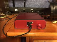
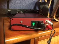
Many thanks to @Wayne for a great amp design and to @6L6 for all the build support he offers. Thanks too to the folks at DIY Store for the circuit board. I just finished up my WHAMMY. It sounds great. I followed 6L6's guide and BOM pretty much to the letter. I went with the OPA2604 but I used a 8-pin socket so I can try other op amps like Muses or Burson. I choose the LED + regulator option #2 as suggested and left out optional capacitors. I used a switched IEC socket with a green lighted switch (hidden on the back side). All of this went into a red Hammond enclosure with a red knob (see pix). I haven't had much time to do a lot of listening but the amp sounds just great driving my LCD-Xs.
I had one amusing problem with the build. I checked the PS function during construction as suggested and the voltages were spot on. I stuffed the rest of the board and assembled it in the case. I turned it on. Nothing! No sound at full volume, not even hiss. I checked all the connections and while I was doing that a lightbulb went off. I opened the case and inserted the OPA2604 in the empty socket. Closed up and turned it on and was stunned by the clarity and definition of the sound I heard. Duh!
If (when?) I build another WHAMMY l'll probably build a wooden case in the workshop. That said I really like the Hammond case option. If I do my own case I'll probably put the inputs on the front of the machine where I prefer them for desktop gear. The audio inputs on the board are in fact right up front next to the volume pot so this should be easy. And of course it will have a blue led on the front panel.
This was my second build in many many years. I built a Camp Amp to tune up for the WHAMMY. The WHAMMY board and guide must be exceptional because even I could complete the project! I did note that my fingers aren't as nimble as they used to be and I need more light and reading glasses to work now. I'm going to quietly hang around the DIY forum and think about my next project.
Attachments
Last edited:
Almost there!
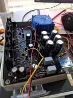
Thank you wayne, 6L6, and everyone in this thread! I've been piecing the WHAMMY together bit by bit, and now it's nearly there. It already sounds amazing, and it pairs beautifully with my Sennheiser HD 660 S headphones. To my ears it sounds much better than connecting directly to the Chord Mojo or the HPA2 headphone amp in the Benchmark DAC 2. In the Kleiber recording of Beethoven's 5th, for example, the sound is lifelike even in the most complicated parts of the recording where dozens of instruments are playing simultaneously. The brass instruments always sound smooth and euphonic instead of shrill or piercing, and it's easy to pick out every instrument. Without the WHAMMY, the instruments sometimes sound like they've been smeared together. I wonder if this happens when an amp doesn't have enough control over the transducer and the waveform loses some of its precision? I've been tinkering with my stereo for over twenty years now, and the review from my wife after hearing my current Qobuz -> Benchmark DAC 2 -> WHAMMY -> Sennheiser HD 660 S signal chain was that it's the best she's ever heard it sound. Kudos to you wayne and 6L6 for this brilliant and budget-friendly amp design and build guide. To quote the wise sages Wayne and Garth, "We're not worthy! We're not worthy!"")
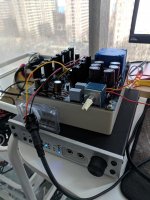
I've attached a few pictures to show my progress.
This is now my second DIY project. The Amp Camp Amp was my first, and as soon as it was finished I was eager to build a Class A amp for my headphones. I'm not an electrical engineer by trade, so whenever I get stuck I've been leaning on this thread and on Youtube for help. Most of my questions so far have revolved around the AC to DC conversion and proper grounding.
I've also made a few comical missteps with my Mouser purchases. I bought this case because the size looked about right, and I thought it would be fun to have a clear plastic cover:
https://www.mouser.com/ProductDetai...8nscVyMMHFQ==&countrycode=US¤cycode=USD
Unfortunately (as you can see in the photos), the PCB doesn't quite fit!
If anyone has time to answer a few newbie questions, this is what I'm still trying to figure out:
1. Is it reasonable to use a plastic or wood case? Should I stick with aluminum because it's important for proper grounding and shielding?
2. In the 6L6 build guide, there is a photo of an orange capacitor between the RCA input ground tabs and the chassis. I'm looking for an appropriate .1 uF capacitor on Mouser, but there is a bewildering array of choices! Would any of those capacitors be fine? Does anyone have tips for narrowing the search to find an appropriate capacitor?
3. Should the ground plane of the PCB ever connect to the ground in the AC wall outlet? Or should the ground in the wall outlet only connect to the chassis and RCA input ground tabs?
4. I realized last night that I mixed up the instructions for C2 and C7 with C13 and C23, and I've been running the amp for ten or twenty hours without C13 and C23. I don't hear anything obviously wrong, but is it possible that I've damaged anything by running it without those components? Does anyone know what those capacitors are responsible for in the circuit?
5. I purchased this volume knob thinking that the 6mm shaft diameter would be a match for the Alps pot, but it doesn't quite fit:
https://www.mouser.com/ProductDetai...a8z%2bLPn5w==&countrycode=US¤cycode=USD
https://www.mouser.com/ProductDetai...yFzrECyPQoA==&countrycode=US¤cycode=USD
Is a "6mm D-Shaft" knob the type that I need to buy instead?
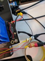
6. Sometimes, when I connect a USB cable from my Macbook Pro to the Benchmark DAC 2, I can hear a buzzing or humming sound when I turn up the volume on the WHAMMY. I also heard a small pop through the WHAMMY when I touched the chassis of the Benchmark DAC. The WHAMMY and Benchmark are plugged into the same wall outlet, and the laptop is plugged into a different outlet. For now I've switched to an optical connection from the laptop, but does this indicate a mistake in my build that could be fixed?
Thanks in advance for any help you can offer!
Thank you wayne, 6L6, and everyone in this thread! I've been piecing the WHAMMY together bit by bit, and now it's nearly there. It already sounds amazing, and it pairs beautifully with my Sennheiser HD 660 S headphones. To my ears it sounds much better than connecting directly to the Chord Mojo or the HPA2 headphone amp in the Benchmark DAC 2. In the Kleiber recording of Beethoven's 5th, for example, the sound is lifelike even in the most complicated parts of the recording where dozens of instruments are playing simultaneously. The brass instruments always sound smooth and euphonic instead of shrill or piercing, and it's easy to pick out every instrument. Without the WHAMMY, the instruments sometimes sound like they've been smeared together. I wonder if this happens when an amp doesn't have enough control over the transducer and the waveform loses some of its precision? I've been tinkering with my stereo for over twenty years now, and the review from my wife after hearing my current Qobuz -> Benchmark DAC 2 -> WHAMMY -> Sennheiser HD 660 S signal chain was that it's the best she's ever heard it sound. Kudos to you wayne and 6L6 for this brilliant and budget-friendly amp design and build guide. To quote the wise sages Wayne and Garth, "We're not worthy! We're not worthy!"
I've attached a few pictures to show my progress.
This is now my second DIY project. The Amp Camp Amp was my first, and as soon as it was finished I was eager to build a Class A amp for my headphones. I'm not an electrical engineer by trade, so whenever I get stuck I've been leaning on this thread and on Youtube for help. Most of my questions so far have revolved around the AC to DC conversion and proper grounding.
I've also made a few comical missteps with my Mouser purchases. I bought this case because the size looked about right, and I thought it would be fun to have a clear plastic cover:
https://www.mouser.com/ProductDetai...8nscVyMMHFQ==&countrycode=US¤cycode=USD
Unfortunately (as you can see in the photos), the PCB doesn't quite fit!
If anyone has time to answer a few newbie questions, this is what I'm still trying to figure out:
1. Is it reasonable to use a plastic or wood case? Should I stick with aluminum because it's important for proper grounding and shielding?
2. In the 6L6 build guide, there is a photo of an orange capacitor between the RCA input ground tabs and the chassis. I'm looking for an appropriate .1 uF capacitor on Mouser, but there is a bewildering array of choices! Would any of those capacitors be fine? Does anyone have tips for narrowing the search to find an appropriate capacitor?
3. Should the ground plane of the PCB ever connect to the ground in the AC wall outlet? Or should the ground in the wall outlet only connect to the chassis and RCA input ground tabs?
4. I realized last night that I mixed up the instructions for C2 and C7 with C13 and C23, and I've been running the amp for ten or twenty hours without C13 and C23. I don't hear anything obviously wrong, but is it possible that I've damaged anything by running it without those components? Does anyone know what those capacitors are responsible for in the circuit?
5. I purchased this volume knob thinking that the 6mm shaft diameter would be a match for the Alps pot, but it doesn't quite fit:
https://www.mouser.com/ProductDetai...a8z%2bLPn5w==&countrycode=US¤cycode=USD
https://www.mouser.com/ProductDetai...yFzrECyPQoA==&countrycode=US¤cycode=USD
Is a "6mm D-Shaft" knob the type that I need to buy instead?
6. Sometimes, when I connect a USB cable from my Macbook Pro to the Benchmark DAC 2, I can hear a buzzing or humming sound when I turn up the volume on the WHAMMY. I also heard a small pop through the WHAMMY when I touched the chassis of the Benchmark DAC. The WHAMMY and Benchmark are plugged into the same wall outlet, and the laptop is plugged into a different outlet. For now I've switched to an optical connection from the laptop, but does this indicate a mistake in my build that could be fixed?
Thanks in advance for any help you can offer!
Attachments
Is a "6mm D-Shaft" knob the type that I need to buy instead?
This is the knob I used on mine:
https://www.amazon.com/gp/product/B0147XGG5I/ref=oh_aui_detailpage_o04_s00?ie=UTF8&psc=1
Thanks @rich1051414!
Hi @baeijsman,
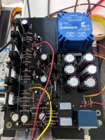
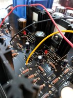
I currently have them aligned with the bottom of the edge of the heatsink. Here's a close-up photo. Does that look correct?
Thanks,
Mark
@mark60615
I know this doesn't answer any of your questions, but you really should flip your Keraterms upside down. As they are now, you would be better off without them.
Hi @baeijsman,
I currently have them aligned with the bottom of the edge of the heatsink. Here's a close-up photo. Does that look correct?
Thanks,
Mark
Attachments
Thanks @wayne!
Alright, so, I've been doing more research, and I think I've made some progress on question 2, the mystery of the orange capacitor. I'll post it here for posterity in case anyone has the same question. @6L6 mentioned previously that ".1 to .47 and at least 50V will work", which I am now pretty confident means .1 to .47 uF. As far as I can tell it's a non-polarized capacitor, so I'll try this .47 uF ceramic capacitor:
https://www.mouser.com/ProductDetail/810-FG26X7R1H474KNT6
Also, I'm taking a stab in the dark here, but it seems like the purpose of that capacitor might be to filter out high frequency noise? Allaboutcircuits.com had this interesting paragraph:
"A cursory glance at a crowded printed-circuit board (PCB) will typically reveal decoupling capacitors scattered throughout, usually located as close as possible to the sensitive DC loads. Capacitor size is usually 0.1 µF or more, a minimum amount of capacitance needed to produce a low enough impedance to short out any noise. Greater capacitance will do a better job at filtering noise, but size and economics limit decoupling capacitors to meager values."
https://www.allaboutcircuits.com/textbook/alternating-current/chpt-8/low-pass-filters/
So that nudged me in the direction of .47 uF over .1 uF, but I'm guessing it won't make make much difference in the end judging by @6L6's post.
This video about different types of capacitors was also very helpful:
https://www.youtube.com/watch?v=e3W0kdLodXo
Last edited:
I've had this in my BOM from reading this thread:
https://www.mouser.com/ProductDetail/505-MKP2D031001FFMKS
And now that you have proposed that a higher value may be better, perhaps this is another option:
https://www.mouser.com/ProductDetai...=sGAEpiMZZMv1cc3ydrPrF7l45uRd9dVh0iRAb7kivhs=
Curious to learn which one would work best and why. Which specific characteristics are we looking for here?
Thanks,
Rafa.
- Home
- Amplifiers
- Pass Labs
- "WHAMMY" Pass DIY headphone amp guide