Fully agree on this one. I am currently using ~6.8ohms output resistor, 22V transformer, and my reg heat sink is much warmer than the output transistor.Also. the transformer is in a plastic capsul.
Do not mix up theatsink temperature with device die temperature.
With 2x22V transformer. and 15V regulators (without the LED's), the regulators must burn off just as much Power as the all of the output transistors combined.
I am thinking of increasing CRCRC resistances to decrease the voltage going in the regs (and by the same occasion further filter out the noise).
I'd have to check that there is still enough juice to drive 32Ohms headphones, but it should be feasible.
Hi all,
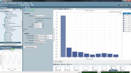
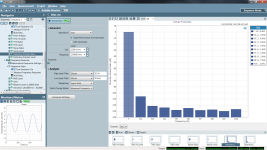
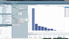
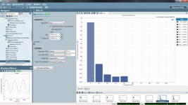
I have been having some fun in trying to learn how to use APX555 and will present my first newbie measurements below.
Tested Whammy config: 22V transformer ; IRF Mosfets; 6.8Ohms output resistor ; OPA2107 Op Amp, 150Ohms load.
I can confirm that the distortion is mainly 2nd harmonic, with an intensity that nicely decreases with harmonic order.
This profile also seems to be consistent among frequencies. (tested 100Hz,1k,4k). Most testings done with 2.5 and 8Vp output.
100hz Left 2.5Vp.png
THD N Left_1k_2.5V.png
THD N Left_1k_8V.png
THD N 4k 2.5V.png
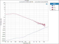
The "THD Ratio" figure (measured at 8Vp) is interesting as it shows the Headphone Output (blue), and the Op Amp output (red/purple), which shows that the Op Amp has to compensate more in low frequencies, and does not seem to be able to correct much higher than 10k (due to MosFet input capacitance maybe?), which, seeing the THD+N numbers, is fine. I recall seeing a constant THD=f(Hz) looking at 6L6 figures, so I am a bit confused.
Op Amp Out R17 THD N 8Vp Left.png
I believe that this figure really shows how well the Op Amp works with the rest of the circuit. I'll measure again with various Op Amps... will be fun
I have been having some fun in trying to learn how to use APX555 and will present my first newbie measurements below.
Tested Whammy config: 22V transformer ; IRF Mosfets; 6.8Ohms output resistor ; OPA2107 Op Amp, 150Ohms load.
I can confirm that the distortion is mainly 2nd harmonic, with an intensity that nicely decreases with harmonic order.
This profile also seems to be consistent among frequencies. (tested 100Hz,1k,4k). Most testings done with 2.5 and 8Vp output.
100hz Left 2.5Vp.png
THD N Left_1k_2.5V.png
THD N Left_1k_8V.png
THD N 4k 2.5V.png
The "THD Ratio" figure (measured at 8Vp) is interesting as it shows the Headphone Output (blue), and the Op Amp output (red/purple), which shows that the Op Amp has to compensate more in low frequencies, and does not seem to be able to correct much higher than 10k (due to MosFet input capacitance maybe?), which, seeing the THD+N numbers, is fine. I recall seeing a constant THD=f(Hz) looking at 6L6 figures, so I am a bit confused.
Op Amp Out R17 THD N 8Vp Left.png
I believe that this figure really shows how well the Op Amp works with the rest of the circuit. I'll measure again with various Op Amps... will be fun
Attachments
Last edited:

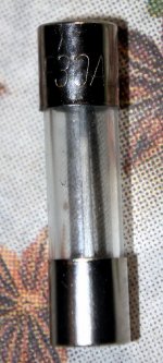
Maybe other that has got the kit (my kit is rather old) should check the provided fuses used for primary. They should probably be around 30-80 mA for 240 VAC (and not 30A).....depending on bias setting.
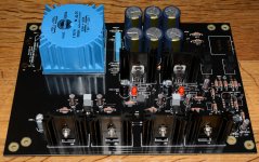
I nearly finished PCB build. I installed the input caps as I measured about 1-2 mV DC on output from DAC. The black Panasonic caps in the kit also looks nice on the black PCB. They have good specs also.
I have not decided on "bias" resistors yet and the two caps close to opamp wait until I have the Burson V6 to check the space needed.
Until now only PSU has been tested.
Attachments
30A ? …..at least it is a F-type.
Is it because you know I like high bias?
Does the IEC have a fuse for live and neutral? You could use the 30A on the neutral side, some countries don't allow fuses on neutral...
No, the big Schurter has only for "Live" and then a place for a spare fuse (all plastic inside). But this Schurter will be used for another future project. It does not fit the Chassis I will use for Whammy. I have plenty of fuses so I find one that fits. But a good idea for some use of the 30A fuse. In M2X chassis I use double fused IEC's.
- Home
- Amplifiers
- Pass Labs
- "WHAMMY" Pass DIY headphone amp guide