WHAMMY variant
Hi PC997,,
I do have some spare boards I don't expect to use. The main board is pretty straight forward with some SOIC's and 0603 passives. The small display and attenuation controller does have a tiny 24 pin leadless package that could be a challenge to solder. I have attached the schematics for each board. You can PM me if you want to pursue it further.
Attachments
Hi PC997,,
I do have some spare boards I don't expect to use. The main board is pretty straight forward with some SOIC's and 0603 passives. The small display and attenuation controller does have a tiny 24 pin leadless package that could be a challenge to solder. I have attached the schematics for each board. You can PM me if you want to pursue it further.
Great information. Thank you so much.
Sure 47 uF Oscons would be fine.
Thank you for that and a great amp.
")
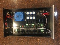
My Whammy is looking about complete, just needs the case finishing
 IMG_20190320_202203 by Garf Arf, on Flickr
I have a couple of ALWSRs set at +/-17Vdc instead of the onboard regs.
Oh, is there any restriction on the capacitance of the signal caps on the input? I have a couple of 3.3uFs I'd like to try.
Odd hum
My second whammy is experiencing an odd hum. When I made it, I used some cheap mic cable for the inputs and outputs, and it had no hum.
I swapped the cheap cable for some pure silver solid core wire I had leftover from another project, and now when I have nothing plugged into the input and I turn up the volume, I get a hum. When I plug in RCA cables and connect them to a source, (still nothing playing), there is no hum.
Any ideas?
Mic cable works better. Go back to it.
I'm gonna guess because of the shielding?
All I have in my junk drawer is quad cable; 4 conductors and shield. Any recommendation on whcih wires to use to for what?
... a reduced size WHAMMY using surface mount components for much of the design ...
This is completely awesome!

You may want to try Mogami Gold mic or instrument cable. It's pretty neutral and super shielded.
Thanks everyone for the advice. I probably have some Mogami mic cable left over from the many headphone cables I've built. I also just got 8 feet of "SC-Square 4-Core MKII" cable to test for a headphone cable, and I can spare a few feet for the Whammy.
I also love that markertek.com sells many cables by the foot with free shipping!
W2534 is $1.59/foot
W2893 is $.99/foot
I believe these are the ones Mogami uses for their gold cables.
I wonder if braiding the home made silver cables I used would help. More curious than anything. I doubt I would be able to hear the difference between the silver or copper cable between the inputs and the board.
I'm gonna guess because of the shielding?
All I have in my junk drawer is quad cable; 4 conductors and shield. Any recommendation on whcih wires to use to for what?
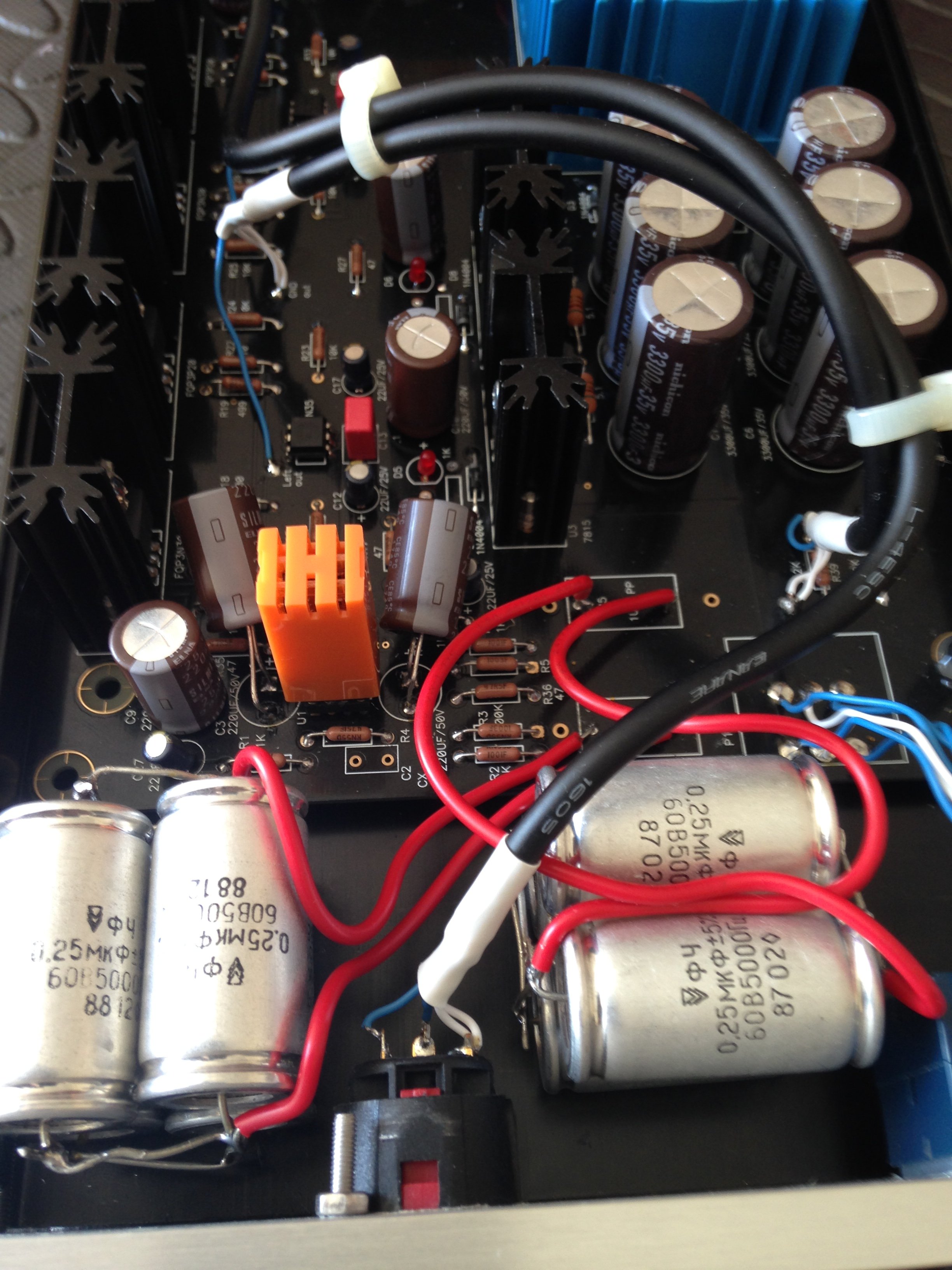
fwiw I used CANARE L-4E5C star quad microphone cable for hooking up my Whammy which was left over from making a replacement headphone cable for my hd800.
Use all 4 connectors just double them up to make pairs when you need a 3 or 2 wire connection.
You can see the white ground cables of the star quad doubled on the headphone jack and pcb in this pic its the same on the rca inputs
Hey 6L6,
I'm getting the boards ready to go so that way once the chassis is available, I'll only need to worry about fitting them in there.
However, I just realized that I never ordered any nuts & bolts for the heatsinks. Is there a part number that you can provide, or the correct size so that way I can grab the correct size? That would be very helpful!
Also, I was curious if I can test the amp out without a chassis -- as long as I'm careful and place it on an insulated pad?
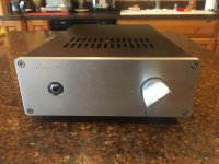
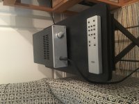
Finished my build yesterday. Has burned in for about 24 hours. Feeding it directly from a Border Patrol DAC and it sounds very nice and is dead quiet. Nice alternative to my Bottlehead S.E.X. Big thanks to Wayne for sharing the design and everyone that worked to put this kit together. 
Attachments
Hi PC997,,
I do have some spare boards I don't expect to use. The main board is pretty straight forward with some SOIC's and 0603 passives. The small display and attenuation controller does have a tiny 24 pin leadless package that could be a challenge to solder. I have attached the schematics for each board. You can PM me if you want to pursue it further.
You are amazing! Great work!
It sings! It's an amazing amp.. But I'm having weird problems.. Currently using a cheapo earphones to test.
Right side keeps getting really hot.. Realised there's a dc offset of 2V on right.. Left is around 13mV that's fine.
Edit.. I have tried measuring offset without the op amp.. It's around - 150mV.. Put the op amp in and it goes to around 10mV for left and right jumps to 2V
But the playback is almost perfect
Any idea?
Last edited:
- Home
- Amplifiers
- Pass Labs
- "WHAMMY" Pass DIY headphone amp guide